VH-2402-L3 specifications
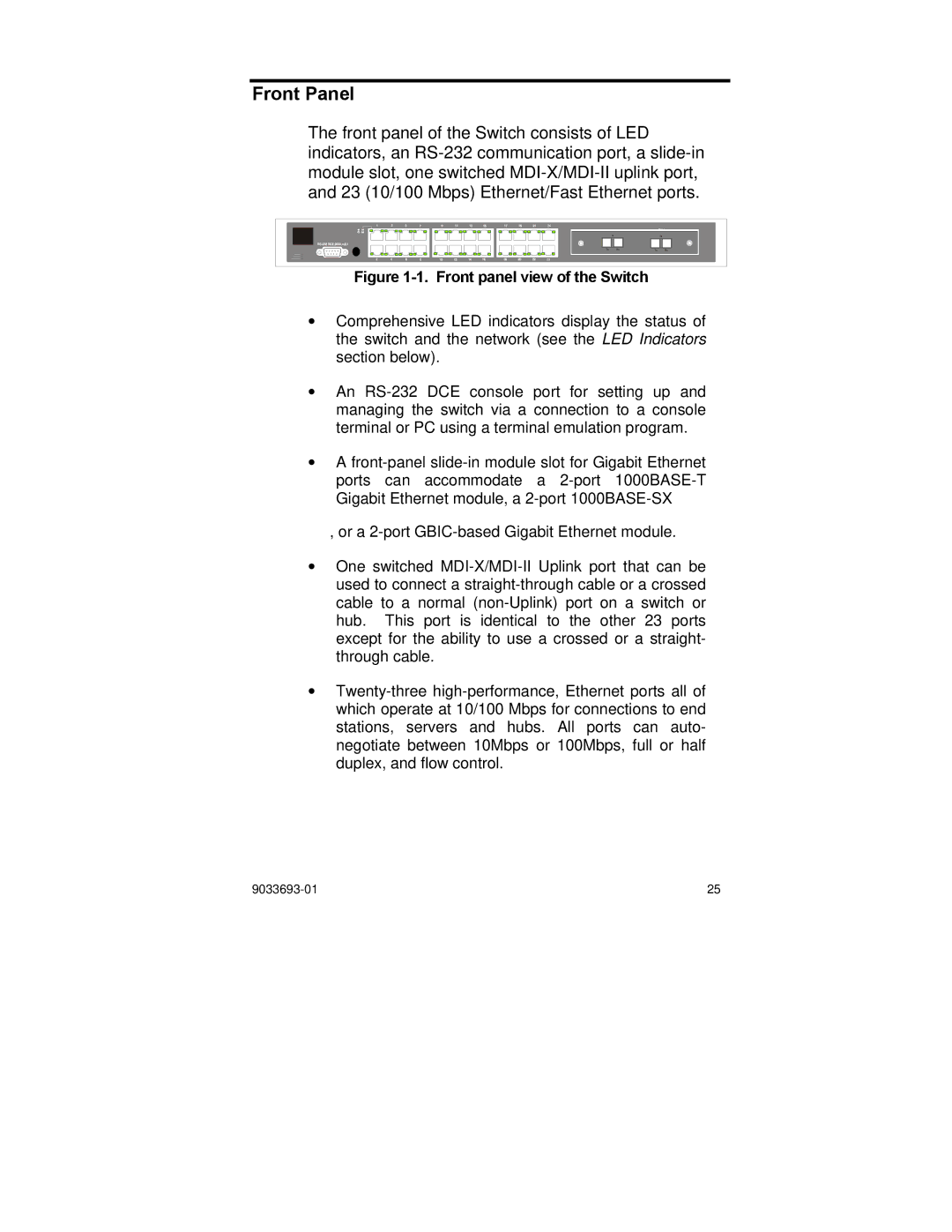
Enterasys Networks VH-2402-L3 is a high-performance Layer 3 switch that blends advanced networking features with robust security measures, catering to the demanding needs of modern enterprise environments. This device is designed to support complex networking requirements and deliver unparalleled efficiency, making it a top choice among IT professionals.One of the main features of the VH-2402-L3 is its impressive port density. It typically includes 24 Gigabit Ethernet ports and can support both copper and fiber connections. This flexibility allows organizations to seamlessly integrate the switch into existing infrastructures without needing extensive upgrades. Additionally, the VH-2402-L3 is equipped with 2 SFP (Small Form-factor Pluggable) slots, which enable the use of various transceiver modules for scalable network expansion.
The VH-2402-L3 leverages advanced Layer 3 routing protocols to ensure optimal data flow across the network. With support for dynamic routing protocols such as RIP, OSPF, and BGP, the switch effectively manages traffic between different subnets, improving overall network efficiency. This capability is essential for enterprises that require reliable inter-VLAN routing and seamless connectivity across multiple network segments.
Embedded security features are another standout characteristic of the VH-2402-L3. It includes support for Access Control Lists (ACLs), VLANs, and IEEE 802.1X authentication, which collectively bolster the security posture of the network. These features help mitigate unauthorized access and ensure that sensitive data remains protected. Additionally, the switch’s built-in support for network segmentation allows IT teams to isolate critical applications and services, further enhancing security.
The VH-2402-L3 also emphasizes ease of management with its user-friendly interface and comprehensive management options. With SNMP (Simple Network Management Protocol), RMON (Remote Monitoring), and a web-based GUI, network administrators can monitor and manage switch performance, configuration, and security with minimal effort.
In conclusion, Enterasys Networks VH-2402-L3 is engineered to meet the challenges of contemporary networking environments. Its blend of high port density, advanced routing capabilities, robust security protocols, and user-friendly management tools makes it a highly reliable solution for organizations seeking to enhance their network infrastructure. Whether for enterprise-level operations or smaller businesses, this switch is designed to provide dynamic performance and ease of use, ensuring that organizations can confidently navigate the complexities of the digital landscape.

