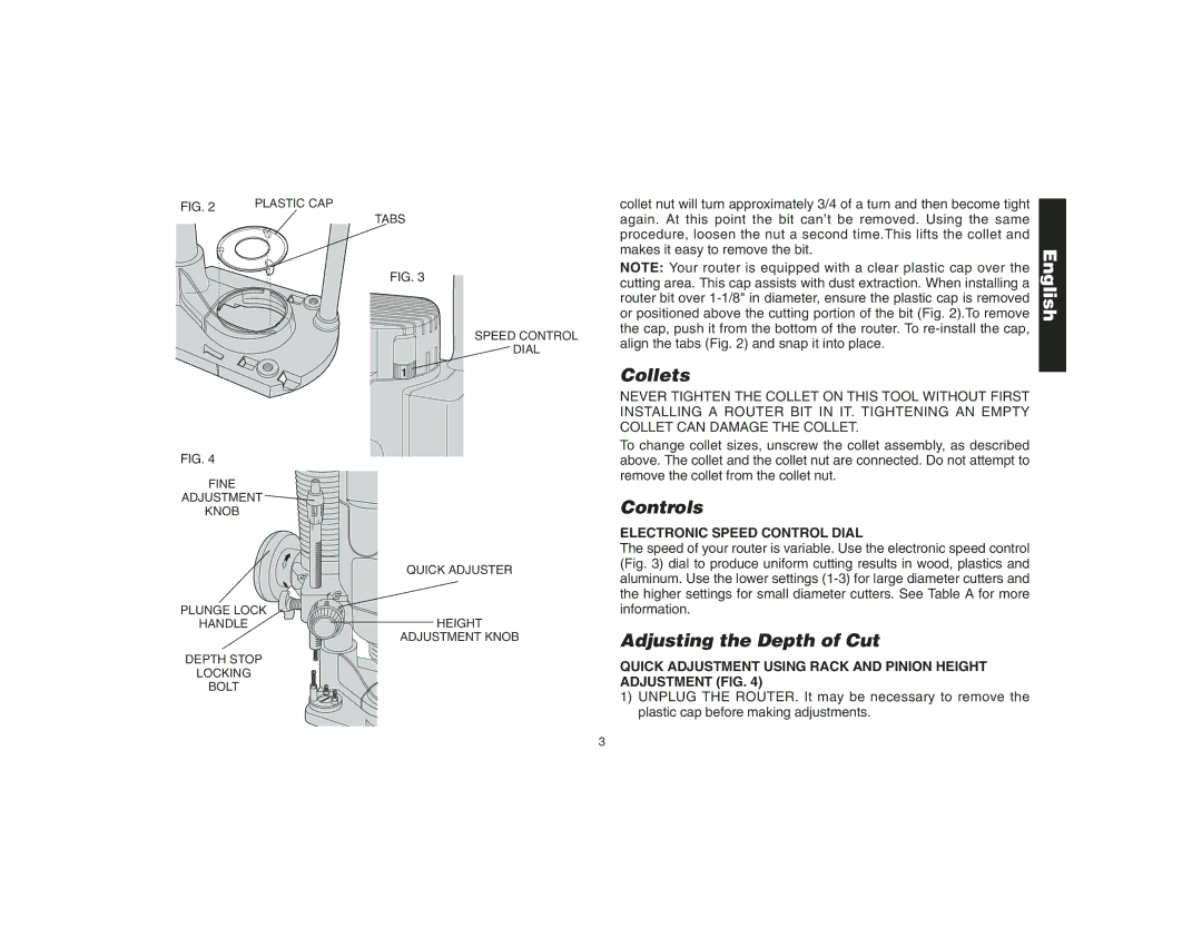
FIG. 2 | PLASTIC CAP |
TABS
FIG. 3
SPEED CONTROL
![]() DIAL
DIAL
FIG. 4
FINE
ADJUSTMENT
KNOB0.
| QUICK ADJUSTER |
PLUNGE LOCK | 5/8 |
3/4 | |
1/2 | |
HANDLE | HEIGHT |
| ADJUSTMENT KNOB |
DEPTH STOP |
|
LOCKING |
|
BOLT |
|
collet nut will turn approximately 3/4 of a turn and then become tight again. At this point the bit can’t be removed. Using the same procedure, loosen the nut a second time.This lifts the collet and makes it easy to remove the bit.
NOTE: Your router is equipped with a clear plastic cap over the cutting area. This cap assists with dust extraction. When installing a router bit over
Collets
NEVER TIGHTEN THE COLLET ON THIS TOOL WITHOUT FIRST INSTALLING A ROUTER BIT IN IT. TIGHTENING AN EMPTY COLLET CAN DAMAGE THE COLLET.
To change collet sizes, unscrew the collet assembly, as described above. The collet and the collet nut are connected. Do not attempt to remove the collet from the collet nut.
Controls
ELECTRONIC SPEED CONTROL DIAL
The speed of your router is variable. Use the electronic speed control (Fig. 3) dial to produce uniform cutting results in wood, plastics and aluminum. Use the lower settings
Adjusting the Depth of Cut
QUICK ADJUSTMENT USING RACK AND PINION HEIGHT ADJUSTMENT (FIG. 4)
1)UNPLUG THE ROUTER. It may be necessary to remove the plastic cap before making adjustments.
English
3