383823-01/DW870 5/3/02 1:33 PM Page 7
To Carry
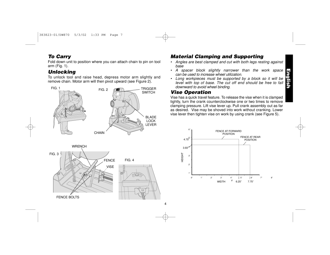
Fold down unit to position where you can attach chain to pin on tool arm (Fig. 1).
Unlocking
To unlock tool and raise head, depress motor arm slightly and remove chain. Motor arm will then pivot upward (see Figure 2).
Material Clamping and Supporting
• | Angles are best clamped and cut with both legs resting against |
| |
• | base | the work space | English |
downward to avoid wheel binding. | |||
A spacer block slightly narrower than |
| ||
can be used to increase wheel utilization.
• Long workpieces must be supported by a block so it will be level with top of base. The cut off end should be free to fall
FIG. 1 | FIG. 2 |
|
CHAIN
WRENCH
FIG. 3
FENCE
VISE
15 30
TRIGGER
SWITCH
BLADE
LOCK
LEVER
FIG. 4
15 | 0 | 15 | 30 | 45 |
30 |
|
|
|
Vise Operation
Vise has a quick travel feature. To release the vise when it is clamped tightly, turn the crank counterclockwise one or two times to remove clamping pressure. Lift vise lever up. Pull crank assembly out as far as desired. Vise may be shoved into work without cranking. Lower vise lever then tighten vise on work by using crank (see Figure 5).
| 6” |
|
| FENCE AT FORWARD |
|
|
| |||
|
|
|
|
|
|
| ||||
|
|
|
|
| POSITION |
|
|
|
| |
| 5” |
|
|
|
|
| FENCE AT REAR |
| ||
| 4.75” |
|
|
|
|
|
| POSITION |
|
|
3.93”4” |
|
|
|
|
|
|
|
|
| |
HEIGHT | 3” |
|
|
|
|
|
|
|
|
|
|
|
|
|
|
|
|
|
|
| |
| 2” |
|
|
|
|
|
|
|
|
|
| 1” |
|
|
|
|
|
|
|
|
|
| 0” | 1” | 2” | 3” |
| 4” | 5” | 6” | 7” | 8” |
|
|
|
| WIDTH | 9” | 6.25” | 7.75” |
|
| |
|
|
|
|
|
|
| ||||
FENCE BOLTS
4