Connecting Personal Computers and Video Equipment
Connections with Component Signals
When the Video Equipment Has a YCbCr Connector or YPbPr Connector
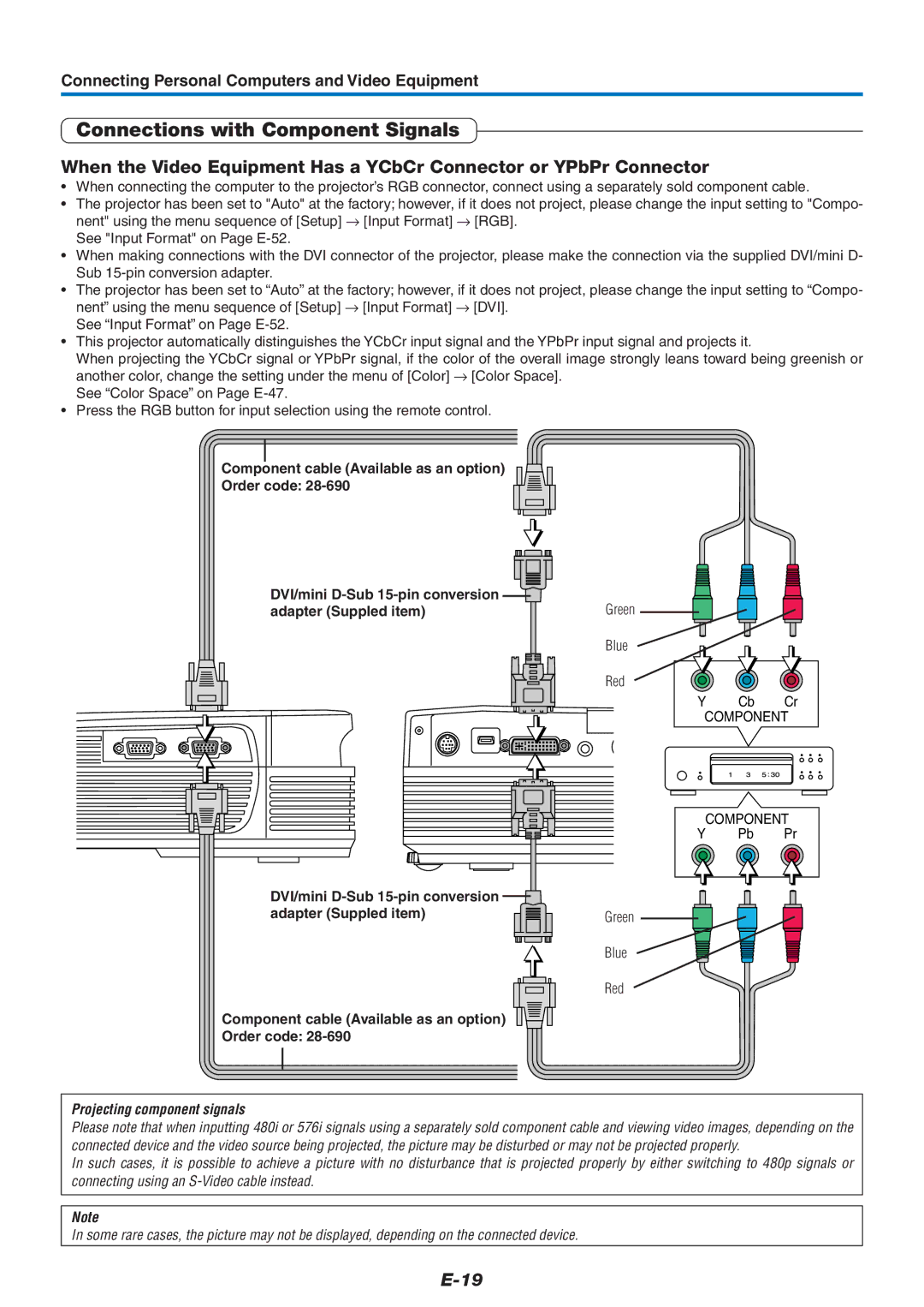
•When connecting the computer to the projector’s RGB connector, connect using a separately sold component cable.
•The projector has been set to "Auto" at the factory; however, if it does not project, please change the input setting to "Compo- nent" using the menu sequence of [Setup] → [Input Format] → [RGB].
See "Input Format" on Page
•When making connections with the DVI connector of the projector, please make the connection via the supplied DVI/mini D- Sub
•The projector has been set to “Auto” at the factory; however, if it does not project, please change the input setting to “Compo- nent” using the menu sequence of [Setup] → [Input Format] → [DVI].
See “Input Format” on Page
•This projector automatically distinguishes the YCbCr input signal and the YPbPr input signal and projects it.
When projecting the YCbCr signal or YPbPr signal, if the color of the overall image strongly leans toward being greenish or another color, change the setting under the menu of [Color] → [Color Space].
See “Color Space” on Page
•Press the RGB button for input selection using the remote control.
Component cable (Available as an option)
Order code:
DVI/mini | Green |
adapter (Suppled item) | |
| Blue |
| Red |
Y Cb Cr
COMPONENT
COMPONENT
Y Pb Pr
DVI/mini |
|
adapter (Suppled item) | Green |
| Blue |
| Red |
Component cable (Available as an option)
Order code:
Projecting component signals
Please note that when inputting 480i or 576i signals using a separately sold component cable and viewing video images, depending on the connected device and the video source being projected, the picture may be disturbed or may not be projected properly.
In such cases, it is possible to achieve a picture with no disturbance that is projected properly by either switching to 480p signals or connecting using an
Note
In some rare cases, the picture may not be displayed, depending on the connected device.
