LBI-38378D
DISASSEMBLY / REASSEMBLY
In the event internal service is required, disassemble the radio in accordance with the following outlined steps. See Figures 6 - 10.
Reassemble the unit by following the steps in reverse order. Observe screw lengths and do not over tighten the screws when reassembling the unit. Torque specifications are listed in Table 3.
CAUTION
ALWAYS remove the battery pack before disassem- bling the unit to avoid blowing the fuse or causing other component damage.
This radio contains CMOS ICs that can be damaged by static electricity. Observe static handling precau-
Tools Required
∙TORXâ T6 Driver
∙M1.5 Hex Driver or Wrench
∙
∙Small
∙Spanner Wrench (top antenna jack)
∙Spanner Wrench (UDC antenna jack)
∙Spanner Wrench (volume control and group/channel switch)
Front and Rear Cover Separation
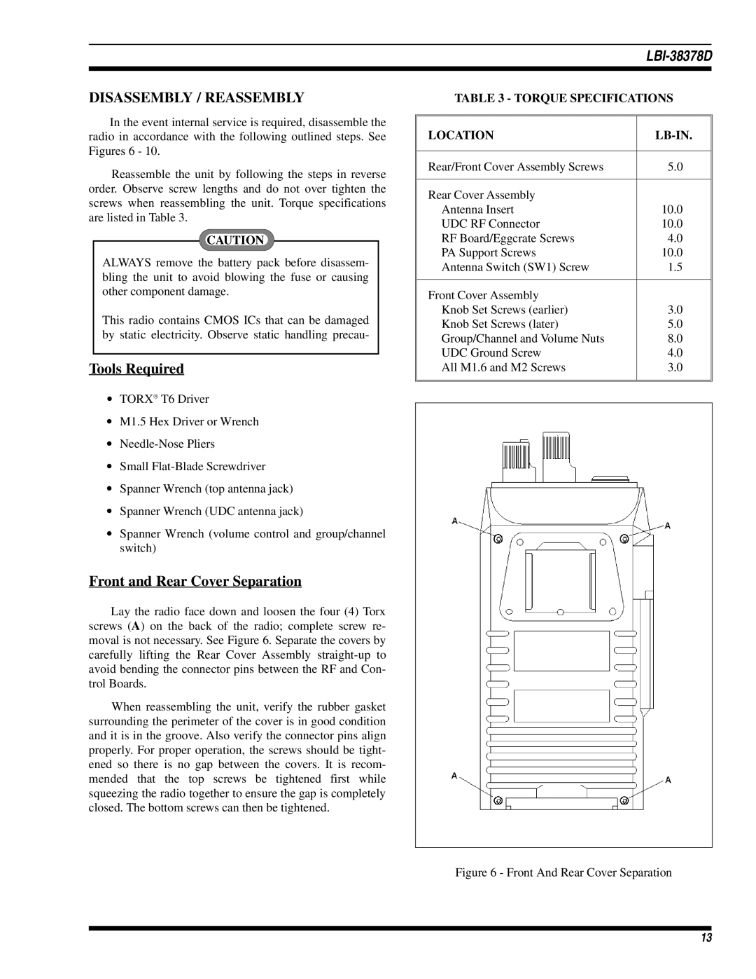
Lay the radio face down and loosen the four (4) Torx screws (A) on the back of the radio; complete screw re- moval is not necessary. See Figure 6. Separate the covers by carefully lifting the Rear Cover Assembly
When reassembling the unit, verify the rubber gasket surrounding the perimeter of the cover is in good condition and it is in the groove. Also verify the connector pins align properly. For proper operation, the screws should be tight- ened so there is no gap between the covers. It is recom- mended that the top screws be tightened first while squeezing the radio together to ensure the gap is completely closed. The bottom screws can then be tightened.
TABLE 3 - TORQUE SPECIFICATIONS
LOCATION |
|
Rear/Front Cover Assembly Screws | 5.0 |
Rear Cover Assembly |
|
Antenna Insert | 10.0 |
UDC RF Connector | 10.0 |
RF Board/Eggcrate Screws | 4.0 |
PA Support Screws | 10.0 |
Antenna Switch (SW1) Screw | 1.5 |
Front Cover Assembly |
|
Knob Set Screws (earlier) | 3.0 |
Knob Set Screws (later) | 5.0 |
Group/Channel and Volume Nuts | 8.0 |
UDC Ground Screw | 4.0 |
All M1.6 and M2 Screws | 3.0 |
|
|
Figure 6 - Front And Rear Cover Separation
13