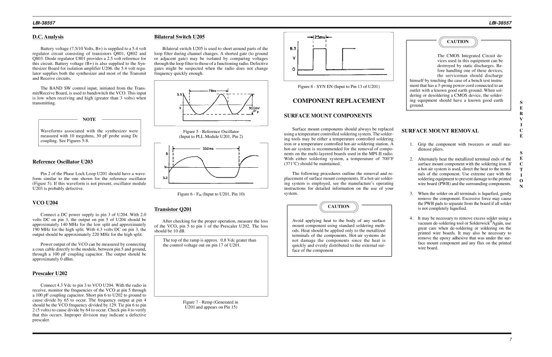
Ericsson MPI-II VHF Component Replacement, D.C. Analysis, Bilateral Switch U205, VCO U204, S E R

Models: MPI-II VHF

1 10
Download 10 pages 48 Kb
Page 8
Image 8
D.C. Analysis

LBI-38557

LBI-38557


D.C. Analysis

Bilateral Switch U205

CAUTION

Battery voltage (7.5/10 Volts, B+) is supplied to a 5.4 volt regulator circuit consisting of transistors Q801, Q802 and Q803. Diode regulator U801 provides a 2.5 volt reference for this circuit. Battery voltage (B+) is also supplied to the Syn- thesizer Board for isolation amplifier U206. the 5.4 volt regu- lator supplies both the synthesizer and most of the Transmit and Receive circuits.

The BAND SW control input, initiated from the Trans- mit/Receive Board, is used to bandswitch the VCO. This input is low when receiving and high (greater than 3 volts) when transmitting.

NOTE

Bilateral switch U205 is used to short around parts of the loop filter during channel changes. A shorted gate (to ground or adjacent gate) may be isolated by comparing voltages through the loop filter to those of a functioning radio. Defective gates might be suspected when the radio does not change frequency quickly enough.

Figure 8 - SYN EN (Input to Pin 13 of U201)

COMPONENT REPLACEMENT

SURFACE MOUNT COMPONENTS

The CMOS Integrated Circuit de- vices used in this equipment can be destroyed by static discharges. Be- fore handling one of these devices, the serviceman should discharge

himself by touching the case of a bench test instru- ment that has a 3-prong power cord connected to an outlet with a known good earth ground. When sol- dering or desoldering a CMOS device, the solder- ing equipment should have a known good earth ground.

S E R V I

Waveforms associated with the synthesizer were measured with 10 megohms, 30 pF probe using Dc coupling. See Figures 5-8.

Figure 5 - Reference Oscillator

(Input to PLL Module U201, Pin 2)

Surface mount components should always be replaced using a temperature controlled soldering system. The solder- ing tools may be either a temperature controlled soldering iron or a temperature controlled hot-air soldering station. A hot-air system is recommended for the removal of compo- nents on the multi-layered boards used in the MPI-II radio.

SURFACE MOUNT REMOVAL

1. Grip the component with tweezers or small nee-

dlenose pliers.

C E

S

Reference Oscillator U203

Pin 2 of the Phase Lock Loop U201 should have a wave- form similar to the one shown for the reference oscillator (Figure 5). If this waveform is not present, oscillator module U203 is probably defective.

VCO U204

Connect a DC power supply to pin 3 of U204. With 2.0 volts DC on pin 3, the output on pin 5 of U204 should be approximately 140 MHz for the low split and approximately 190 MHz for the high split. With 4.3 volts DC on pin 3, the output should be approximately 220 MHz for the high split.

Power output of the VCO can be measured by connecting a coax cable directly to the module, between pin 5 and ground, through a 100 pF coupling capacitor. The output should be approximately 0 dBm.

Prescaler U202

Connect 4.3 Vdc to pin 3 to VCO U204. With the radio in receive, monitor the frequencies of the VCO at pin 5 through a 100 pF coupling capacitor. Short pin 6 to U202 to ground to cause divide by 65 to occur. The frequency output at pin 4 should be the VCO frequency divided by 129. Tie pin 6 to pin 2 (5 volts) to cause divide by 64 to occur. Check pin 4 to verify that this occurs. Improper division may indicate a defective prescaler.

Figure 6 - Fin (Input to U201, Pin 10)

Transistor Q201

After checking for the proper operation, measure the loss of the VCO, pin 5 to pin 1 of the Prescaler U202. The loss should be 10 dB.

The top of the ramp is approx. 0.8 Vdc geater than the control voltage out on pin 17 of U201.

Figure 7 - Remp (Generated in

U201 and appears on Pin 15)

With either soldering system, a temperature of 700°F (371°C) should be maintained.

The following procedures outline the removal and re- placement of surface mount components. If a hot-air solder- ing system is employed, see the manufacture’s operating instructions for detailed information on the use of your system.

CAUTION

Avoid applying heat to the body of any surface mount component using standard soldering meth- ods. Heat should be applied only to the metallized terminals of the components. Hot-air systems do not damage the components since the heat is quickly and evenly distributed to the external sur- face of the component

2. Alternately heat the metallized terminal ends of the

surface mount component with the soldering iron. If

a hot-air system is used, direct the heat to the termi-

nals of the component. Use extreme care with the

soldering equipment to prevent damage to the printed

wire board (PWB) and the surrounding components.

3. When the solder on all terminals is liquefied, gently

remove the component. Excessive force may cause

the PWB pads to separate from the board if all solder

is not completely liquefied.

4. It may be necessary to remove excess solder using a

vacuum de-soldering tool or Solderwick® Again, use

great care when de-soldering or soldering on the

printed wire boards. It may also be necessary to

remove the epoxy adhesive that was under the sur-

face mount component and any flux on the printed

wire board.

E C T I O N

7

Page 8
Image 8
Ericsson MPI-II VHF Component Replacement, D.C. Analysis, Bilateral Switch U205, Surface Mount Components, VCO U204, S E R