SURFACE MOUNT COMPONENT REPLACEMENT
1."Tin" one terminal end of the new component and the corresponding pad of the PWB. Use as little solder as possible.
2.Place the component on the PWB pads, observing proper orientation for capacitors, diodes, transistors, etc.
3.Simultaneously touch the "tinned" terminal end and the "tinned" pad with the soldering iron. Slightly press the component down on the board as the solder liquifies. Solder all terminals, allowing the compo- nent time to cool between each application of heat. Do not apply heat for an excessive length of time and do not use excessive solder.
With a hot-air system, apply hot air until all "tinned" areas are melted and the component is seated in place. It may be necessary to slightly press the component down on the board. Touch-up the soldered connections with a standard soldering iron if needed. Do not use excessive solder.
CAUTION
Some chemicals may damage the internal and ex- ternal plastic parts of the MPI-II unit.
4.Allow the component and the board to cool and then remove all flux from the area using alcohol or another GE approved flux remover.
If a hot-air system is not available, the service technician may wish to clip the pins near the body of the defective IC and remove it. The pins can then be removed from the PWB with a standard soldering iron and tweezers, and the new IC installed following the Surface Mount Component Replace- ment procedures. It may not be necessary to "tin" all (or any) of the IC pins before the installation process.
MODULE REPLACEMENT
The modules, all of which are located on the Synthe- sizer Board, are very reliable devices. Before replacing any of the modules, check the associated circuitry thoroughly to insure there is not a problem elsewhere. If replacement is necessary, follow the below procedures.
All of the component lead holes on the Synthesizer Board for the modules are plated through from the top to the bottom of the board. This allows for easy removal and replacement of the modules as long as appropriate soldering techniques are observed. Always observe static precautions when handling the board during module replacement.
To remove a module, position the Synthesizer Board in a work vice (face down, chip components up) and remove the solder from the plated-through points at the appropriate pins. If a hot-air system is employed, use an appropriate tip that will localize the heat on the pins and not on surrounding chip components. Solderwick® or a vacuum de-soldering iron will also remove the solder if a hot-air station is not available. When all solder has been removed or liquefied, the module should drop out of the eggcrate casting.
To install a module, clean any solder from the plated through holes and clean all flux from the board. Next, install the replacement module making sure that all pins align in the proper holes on the Synthesizer Board. Resolder the pins to the board. Clean the flux from the board using an approved solvent and clip any excess lead length.
5.Check the receiver sensitivity.
6.Check receiver audio.
7.If not using speaker/microphone, be sure the Accessory Jack Cover is securely in place.
BATTERY INFORMATION
The MPI-II radio uses a Nickel Cadmium battery. Two watt radios use a 7.5 volt battery (19D900639G6) and four watt radios use a 10 volt battery (19D900639G7). The batteries are sealed at the factory and are not serviceable other than regular cleaning of the contacts. Table 3 below provides the current consumption for different operating conditions.
Table 3 - Battery Drain
| | | | |
| | 2 WATT RADIOS | 4 WATT RADIOS | |
| | 7.5 VOLTS | 10 VOLTS | |
| | | | |
| | | | |
| Receiver | 36 mA | 36 mA | |
| Standby | | | |
| | | | |
| Receiver | 200 mA | 200 mA | |
| Full Audio | | | |
| | | | |
| Transmit | 750 mA | 1050 mA | |
| | | | |
| | | | |
REDUCED CAPACITY
Nickel-Cadmium batteries in some applications can de- velop a condition of reduced capacity, sometimes called "Memory Effect". This cndition may occur when:
1. The battery is continuously overcharged for long peri- |
ods of time. |
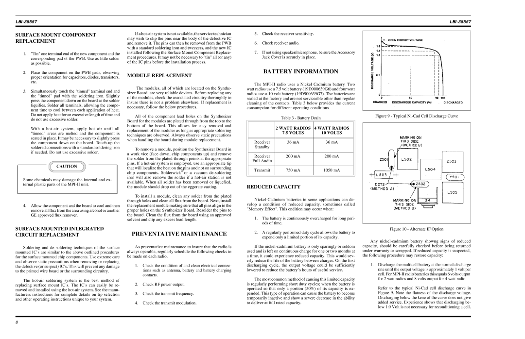
Figure 9 - Typical Ni-Cad Cell Discharge Curve
Soldering and de-soldering techniques of the surface mounted IC’s are similar to the above outlined procedures for the surface mounted chip components. Use extreme care and observe static precautions when removing or replacing the defective (or suspect) IC’s. This will prevent any damage to the printed wire board or the surrounding circuitry.
The hot-air soldering system is the best method of replacing surface mount IC’s. The IC’s can easily be re- moved and installed using the hot-air system. See the manu- facturers instructions for complete details on tip selection and other operating instructions unique to your system.
As preventative maintenance to insure that the radio is always operable, regularly schedule the following checks to be made on each radio.
1.Check the condition of and clean electrical connec- tions such as antenna, battery and battery charging contacts.
2.Check RF power output.
3.Check the transmit frequency.
4.Check the transmit modulation.
If the nickel-cadmium battery is only sparingly or seldom used and is left on continuous charge for one or two months at a time, it could experience reduced capacity. This would sev- erly reduce the life of the battery between charges. On the first discharging cycle, the output voltage could be sufficiently lowered to reduce the battery’s hours of useful service.
The most common method of causing this limited capacity is regularly performing short duty cycles; when the battery is operated so that only a portion (50%) of its capacity is ex- pended. This type of operation can cause the battery to become temporarily inactive and show a severe decrease in the ability to deliver at full rated capacity.
Any nickel-cadmium battery showng signs of reduced capacity, should be carefully checked before being returned under warranty or scrapped. If reduced capacity is suspected, the following procedure may restore capacity:
1.Discharge the multicell battery at the normal discharge rate until the output voltage is approximately 1 volt per cell. For MPI-II radio batteries thisequals 6 volts output for 2 watt radios and 8 volts output for 4 watt radio.
Refer to the typical Ni-Cad cell discharge curve in Figure 9. Note the flatness of the discharge voltage. Discharging below the kene of the curve does not give added service. Experience shows that discharging be- low 1.0 Volt is not necessary for reconditioning a cell.