Microphone Preamplifier specifications
The Eureka Microphone Preamplifier is a versatile and high-performance tool designed for audio professionals seeking clarity and detail in their recordings. Known for its exceptional sound quality and innovative features, the Eureka has become a popular choice for both studio and live sound applications.One of the standout features of the Eureka is its Class A vacuum tube circuitry, which provides a warm and rich tonal character to the audio signal. This analog warmth is complemented by the preamp's exceptional bandwidth, allowing for a natural representation of the sound source. The use of high-quality components contributes to its low noise floor, ensuring that even the most delicate sounds are captured with precision.
The Eureka preamp is equipped with an impressive gain range, enabling users to amplify their microphones effectively without compromising sound quality. Its gain is adjustable up to 64 dB, which makes it suitable for a wide variety of microphones, including low-output dynamic mics and high-sensitivity condenser mics. This flexibility ensures that it can adapt to any recording scenario, whether it's capturing vocals, instruments, or ambient sounds.
Another noteworthy characteristic of the Eureka is its built-in high-pass filter, which eliminates unwanted low-frequency rumble and wind noise. This feature is particularly advantageous for field recording and live situations, allowing users to achieve a cleaner and more focused sound. Additionally, the preamp features a phase reverse switch, which is essential for combating phase issues when using multiple microphones.
The Eureka's user-friendly design includes LED metering for input level monitoring, providing real-time feedback on the signal's strength. This visual aid helps engineers make informed decisions about gain settings, ensuring optimal headroom and preventing clipping.
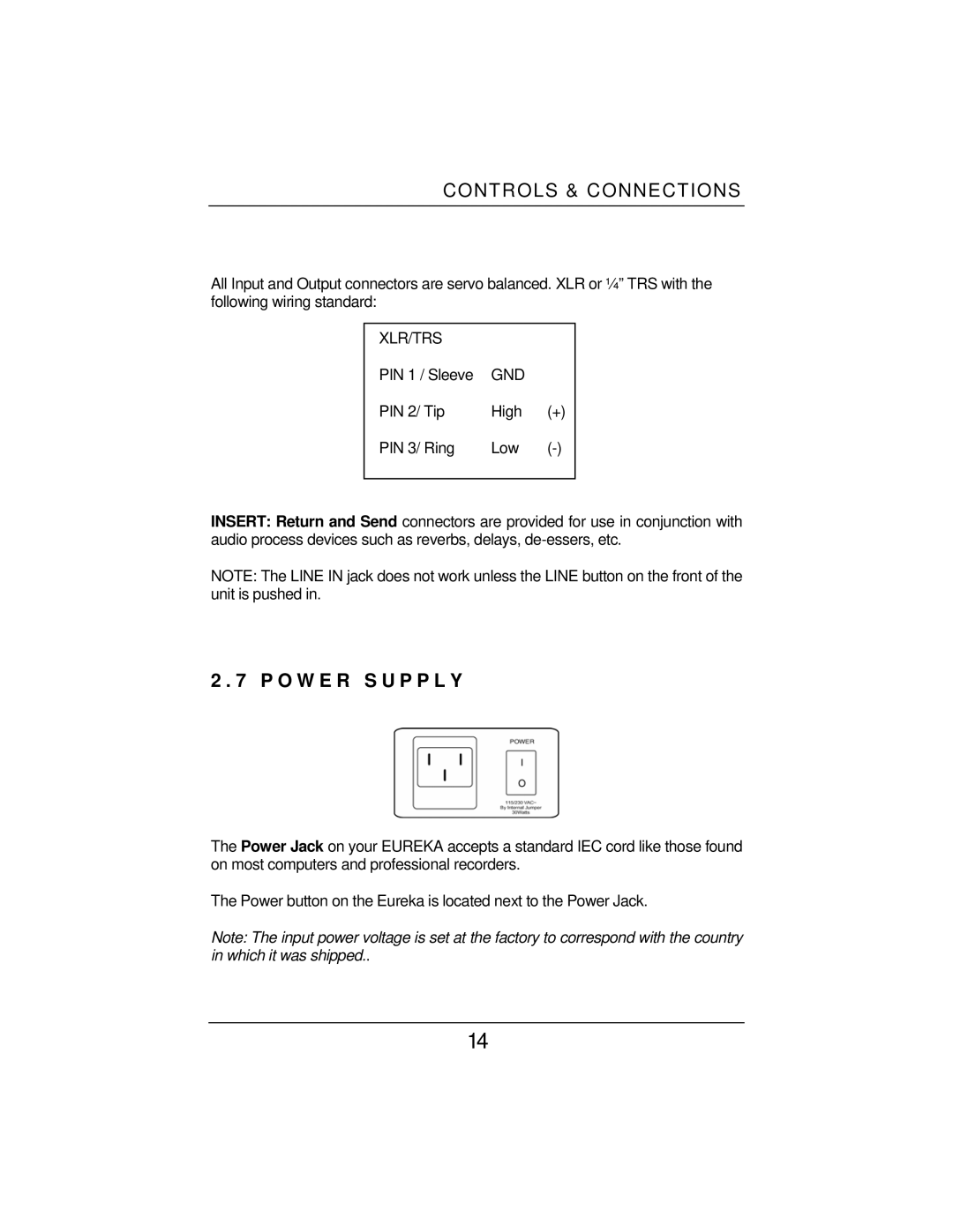
For connectivity, the Eureka offers both XLR and 1/4-inch outputs, making it compatible with a wide range of audio interfaces and mixing consoles. The robust build quality ensures that it withstands the rigors of both studio and live environments, making it a reliable choice for audio professionals.
In summary, the Eureka Microphone Preamplifier combines advanced technology with practical features, delivering outstanding sound quality and versatility. Its Class A vacuum tube circuitry, adjustable gain, high-pass filter, and solid build make it an essential tool for anyone serious about their audio recordings.

