8 | Application Note | ||
|
|
|
|
Comparing the
Table 1.
|
| Realtek RTL8139 version |
| |
|
|
|
|
|
| Till S.N. 229904389 |
| B |
|
|
|
|
|
|
| Starting from 03M241 S.N. 229904390 |
| C |
|
Ethernet interface
The
J4 for a 10/100 Ethernet (LAN) connection. J4 is a 5x2 pin – 2.54mm step connector
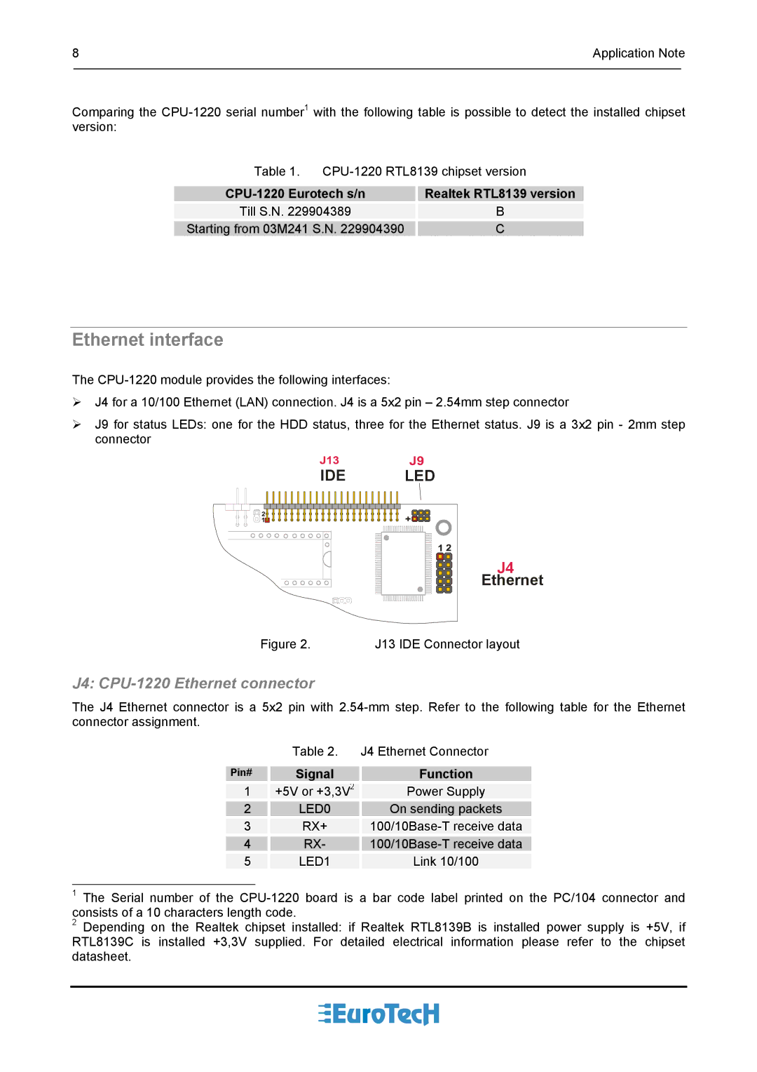
J9 for status LEDs: one for the HDD status, three for the Ethernet status. J9 is a 3x2 pin - 2mm step connector
IDE | LED |
| J4 |
| Ethernet |
Figure 2. | J13 IDE Connector layout |
J4: CPU-1220 Ethernet connector
The J4 Ethernet connector is a 5x2 pin with
| Table 2. | J4 Ethernet Connector |
Pin# | Signal | Function |
1 | +5V or +3,3V2 | Power Supply |
2 | LED0 | On sending packets |
3 | RX+ | |
4 | RX- | |
5 | LED1 | Link 10/100 |
1The Serial number of the
2Depending on the Realtek chipset installed: if Realtek RTL8139B is installed power supply is +5V, if RTL8139C is installed +3,3V supplied. For detailed electrical information please refer to the chipset datasheet.