Application Note | 9 | ||
|
|
|
|
6 | GND | Ground signal |
7 | LED2 | On receiving packets |
8 | GND | Ground signal |
9 | TX+ | |
10 | TX- |
J9: Status LEDs
The HDD and Ethernet activity LEDs are implemented on the J9 connector. It is a 3x2 pin - 2mm step. The following table shows the J9 connector pinout:
| Table 3. | J9 LED Connector |
Pin | Signal | Function |
1 | VDD | IDE LED anode |
2 | IDE LED | IDE LED cathode |
3 | 5V_LAN | LAN LEDs |
|
| common anode |
4 | LAN LED 2 | LAN LED cathode |
5 | LAN LED 0 | LAN LED cathode |
6 | LAN LED 1 | LAN LED cathode |
The meaning of LAN LEDs is the following: LAN LED 0: TX
LAN LED 1: Link 10/100 (LAN LED 1 signals that the correct connection is established)
LAN LED 2: RX
Ethernet physical adapter
![]()
![]()
![]() Note: To establish a connection to the Ethernet, the Eurotech Ethernet Adapter can be plugged
Note: To establish a connection to the Ethernet, the Eurotech Ethernet Adapter can be plugged ![]() between the CPU board (to the J4 connector) and the net cable.
between the CPU board (to the J4 connector) and the net cable.
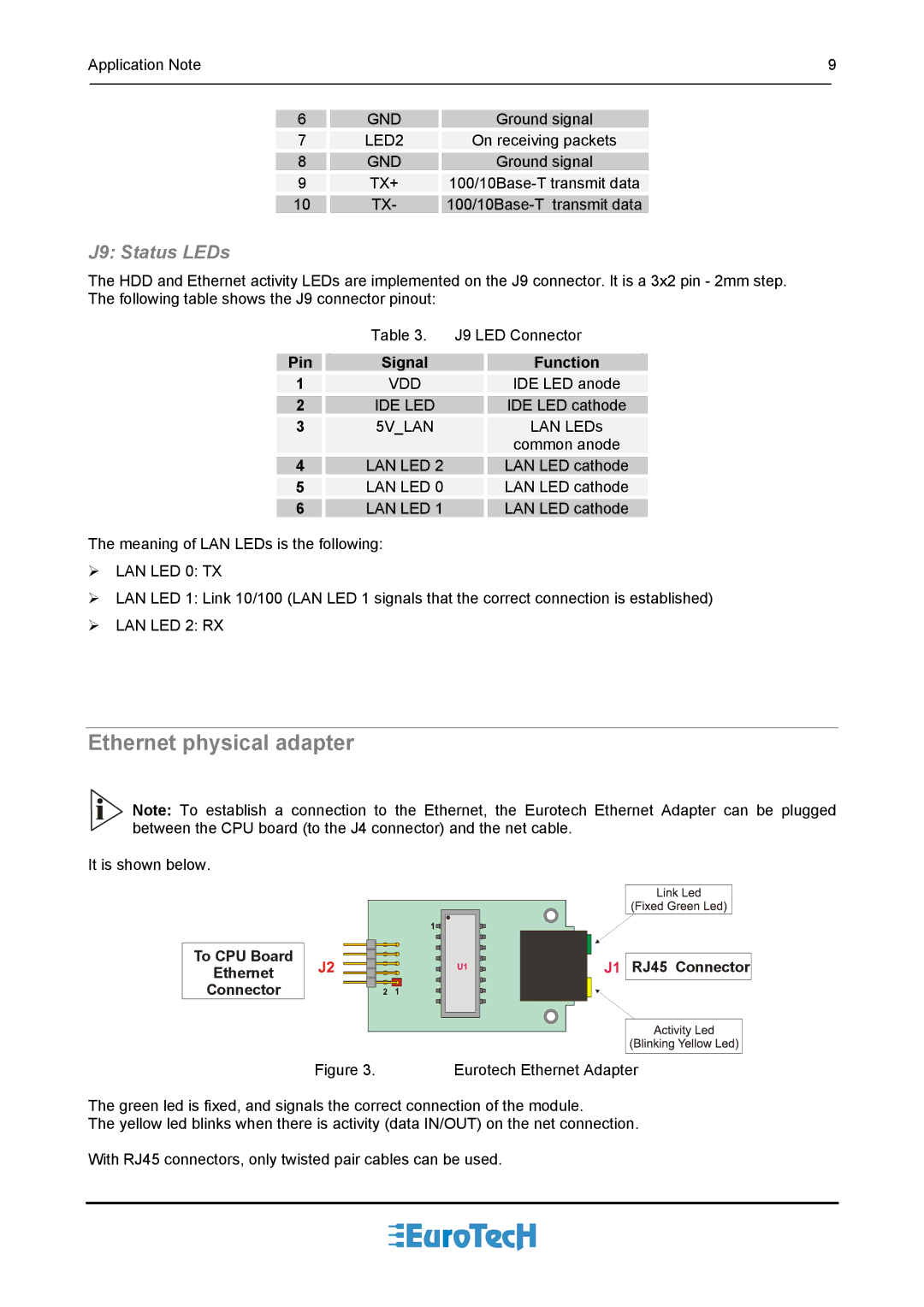
It is shown below.
To CPU Board
Ethernet
Connector
Figure 3.


 RJ45 Connector
Eurotech Ethernet Adapter
The green led is fixed, and signals the correct connection of the module.
The yellow led blinks when there is activity (data IN/OUT) on the net connection.
With RJ45 connectors, only twisted pair cables can be used.
