8
20/20p POWERED MONITOR CONNECTIONS AND OPERATION
Please refer to Figure 3.
1CHANNEL A The Channel A amplifier section powers the external passive 20/20 monitor through the A output connector.
2CHANNEL B The Channel B amplifier section powers the internal 20/20 monitor.
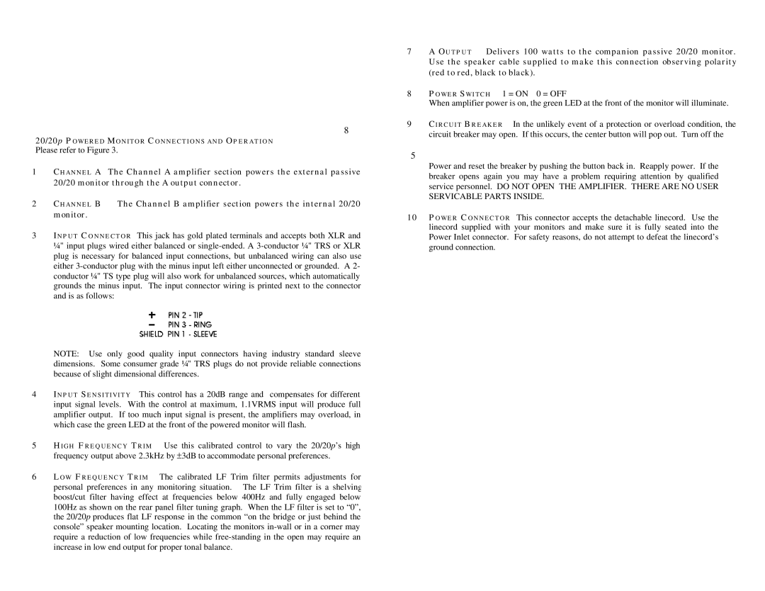
3INPUT CONNECTOR This jack has gold plated terminals and accepts both XLR and ¼" input plugs wired either balanced or
| NOTE: Use only good quality input connectors having industry standard sleeve |
| dimensions. Some consumer grade ¼" TRS plugs do not provide reliable connections |
| because of slight dimensional differences. |
4 | INPUT SENSITIVITY This control has a 20dB range and compensates for different |
| input signal levels. With the control at maximum, 1.1VRMS input will produce full |
| amplifier output. If too much input signal is present, the amplifiers may overload, in |
| which case the green LED at the front of the powered monitor will flash. |
5HIGH FREQUENCY TRIM Use this calibrated control to vary the 20/20p’s high frequency output above 2.3kHz by ±3dB to accommodate personal preferences.
6LOW FREQUENCY TRIM The calibrated LF Trim filter permits adjustments for personal preferences in any monitoring situation. The LF Trim filter is a shelving boost/cut filter having effect at frequencies below 400Hz and fully engaged below 100Hz as shown on the rear panel filter tuning graph. When the LF filter is set to “0”, the 20/20p produces flat LF response in the common “on the bridge or just behind the console” speaker mounting location. Locating the monitors
7A OUTPUT Delivers 100 watts to the companion passive 20/20 monitor. Use the speaker cable supplied to make this connection observing polarity (red to red, black to black).
8 POWER SWITCH 1 = ON 0 = OFF
When amplifier power is on, the green LED at the front of the monitor will illuminate.
9CIRCUIT BREAKER In the unlikely event of a protection or overload condition, the circuit breaker may open. If this occurs, the center button will pop out. Turn off the
5
Power and reset the breaker by pushing the button back in. Reapply power. If the breaker opens again you may have a problem requiring attention by qualified service personnel. DO NOT OPEN THE AMPLIFIER. THERE ARE NO USER SERVICABLE PARTS INSIDE.
10POWER CONNECTOR This connector accepts the detachable linecord. Use the linecord supplied with your monitors and make sure it is fully seated into the Power Inlet connector. For safety reasons, do not attempt to defeat the linecord’s ground connection.