INSTALLATION, continued
BEFORE YOU BEGIN INSTALLATION
This unit is designed to be mounted on any standard wiring junction box up to a
This Alarm must have AC or battery power to operate. If the AC power fails, the battery
Find the pair of
•On each label write in the phone number of your emergency responder (like 911) and a qualified appliance technician.
•Place one label near the CO Alarm, and the other label in the “fresh air” location you plan to go if the alarm sounds.
NOTE: A qualified appliance technician is defined as “a person, firm, corporation, or company that either in person or through a representative, is engaged in and responsible for the installation, testing, servicing, or replacement of heating, ventilation, air conditioning (HVAC) equipment, combustion appliances and equipment, and/or gas fire- places or other decorative combustion equipment.”
STAND ALONE ALARM ONLY:
•If you are only installing one unit, restore power to the junction box.
INTERCONNECTED ALARMS ONLY:
•If you are interconnecting multiple Alarms, repeat Step
ELECTRICAL SHOCK HAZARD. Do not restore power until all Alarms are completely installed. Restoring power before installation is complete may result in serious electrical shock, injury or death.
6. | Make sure the CO Alarm is receiving AC power. Under normal operation,the red indicator light will shine continu- | |
| ously. If the red power indicator light does not light, TURN OFF POWER TO THE JUNCTION BOX and | |
| recheck all connections. If all connections are correct and the red power indicator still does not light when | |
| you restore the power, the unit should be replaced immediately. | |
7. | ACTIVATING THE BATTERY | |
|
| |
|
|
|
| Activate the battery | |
| open the battery compartment and reposition the battery during installation. DO NOT remove the battery | |
| activation tab until AC power is turned on to conserve battery power. | |
8. | Test the CO Alarm. Press and hold the test button on the cover until the alarm sounds: 4 beeps, pause, | |
| 4 beeps, pause. In a series of interconnected Alarms, you must test each Alarm separately by pressing and | |
1 | 3 |
![]() 2
2
2
![]() 6
6
3
4 | 5 |
|
7 ![]()
![]()
8
9
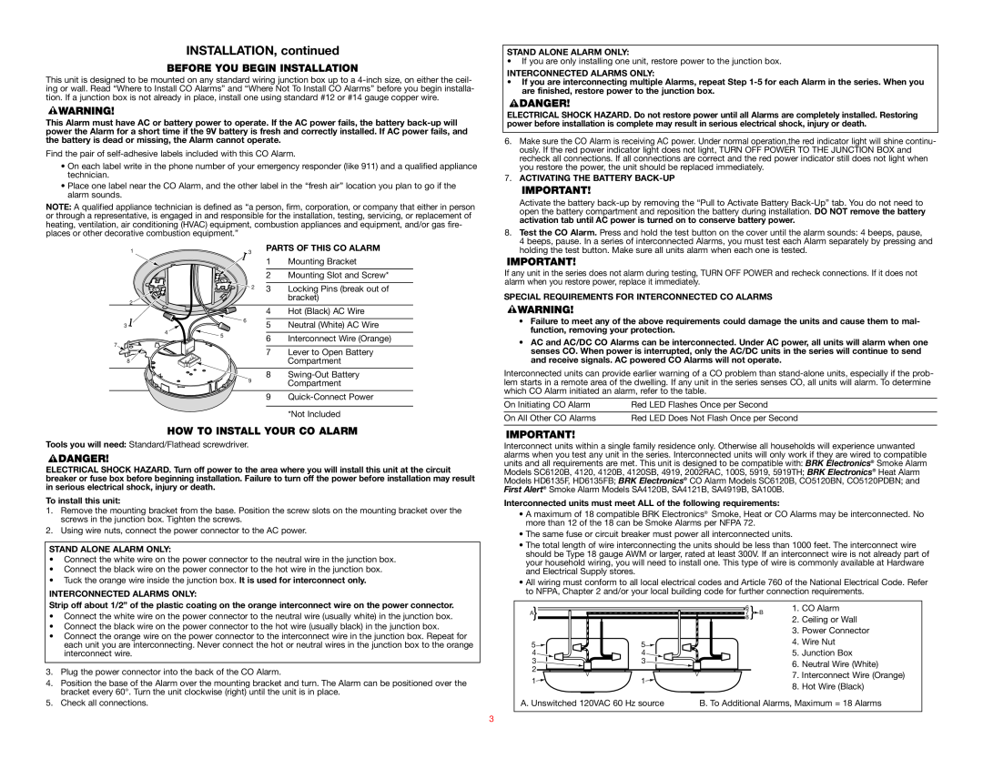
PARTS OF THIS CO ALARM
1Mounting Bracket
2Mounting Slot and Screw*
3Locking Pins (break out of bracket)
4Hot (Black) AC Wire
5Neutral (White) AC Wire
6Interconnect Wire (Orange)
7Lever to Open Battery Compartment
8
9
holding the test button. Make sure all units alarm when each one is tested. |
If any unit in the series does not alarm during testing, TURN OFF POWER and recheck connections. If it does not alarm when you restore power, replace it immediately.
SPECIAL REQUIREMENTS FOR INTERCONNECTED CO ALARMS
•Failure to meet any of the above requirements could damage the units and cause them to mal- function, removing your protection.
•AC and AC/DC CO Alarms can be interconnected. Under AC power, all units will alarm when one senses CO. When power is interrupted, only the AC/DC units in the series will continue to send and receive signals. AC powered CO Alarms will not operate.
Interconnected units can provide earlier warning of a CO problem than
On Initiating CO Alarm | Red LED Flashes Once per Second |
On All Other CO Alarms | Red LED Does Not Flash Once per Second |
HOW TO INSTALL YOUR CO ALARM
Tools you will need: Standard/Flathead screwdriver.
ELECTRICAL SHOCK HAZARD. Turn off power to the area where you will install this unit at the circuit breaker or fuse box before beginning installation. Failure to turn off the power before installation may result in serious electrical shock, injury or death.
To install this unit:
1.Remove the mounting bracket from the base. Position the screw slots on the mounting bracket over the screws in the junction box. Tighten the screws.
2.Using wire nuts, connect the power connector to the AC power.
STAND ALONE ALARM ONLY:
•Connect the white wire on the power connector to the neutral wire in the junction box.
•Connect the black wire on the power connector to the hot wire in the junction box.
•Tuck the orange wire inside the junction box. It is used for interconnect only.
INTERCONNECTED ALARMS ONLY:
Strip off about 1/2” of the plastic coating on the orange interconnect wire on the power connector.
•Connect the white wire on the power connector to the neutral wire (usually white) in the junction box.
•Connect the black wire on the power connector to the hot wire (usually black) in the junction box.
•Connect the orange wire on the power connector to the interconnect wire in the junction box. Repeat for each unit you are interconnecting. Never connect the hot or neutral wires in the junction box to the orange interconnect wire.
3.Plug the power connector into the back of the CO Alarm.
4.Position the base of the Alarm over the mounting bracket and turn. The Alarm can be positioned over the bracket every 60°. Turn the unit clockwise (right) until the unit is in place.
5.Check all connections.
Interconnect units within a single family residence only. Otherwise all households will experience unwanted alarms when you test any unit in the series. Interconnected units will only work if they are wired to compatible units and all requirements are met. This unit is designed to be compatible with: BRK Electronics® Smoke Alarm Models SC6120B, 4120, 4120B, 4120SB, 4919, 2002RAC, 100S, 5919, 5919TH; BRK Electronics® Heat Alarm Models HD6135F, HD6135FB; BRK Electronics® CO Alarm Models SC6120B, CO5120BN, CO5120PDBN; and First Alert® Smoke Alarm Models SA4120B, SA4121B, SA4919B, SA100B.
Interconnected units must meet ALL of the following requirements:
•A maximum of 18 compatible BRK Electronics® Smoke, Heat or CO Alarms may be interconnected. No more than 12 of the 18 can be Smoke Alarms per NFPA 72.
•The same fuse or circuit breaker must power all interconnected units.
•The total length of wire interconnecting the units should be less than 1000 feet. The interconnect wire should be Type 18 gauge AWM or larger, rated at least 300V. If an interconnect wire is not already part of your household wiring, you will need to install one. This type of wire is commonly available at Hardware and Electrical Supply stores.
•All wiring must conform to all local electrical codes and Article 760 of the National Electrical Code. Refer to NFPA, Chapter 2 and/or your local building code for further connection requirements.
A} | 6 | } |
| 1. | CO Alarm |
87 | B | 2. | Ceiling or Wall | ||
|
|
|
| ||
|
|
|
| 3. | Power Connector |
5 | 5 |
|
| 4. | Wire Nut |
4 | 4 |
|
| 5. | Junction Box |
3 | 3 |
|
| 6. | Neutral Wire (White) |
2 |
|
|
| ||
|
|
|
|
|
1 | 1 | 7. Interconnect Wire (Orange) | |
8. Hot Wire (Black) | |||
|
| ||
|
| ||
A. Unswitched 120VAC 60 Hz source | B. To Additional Alarms, Maximum = 18 Alarms | ||
3