PowerCage 1600 Enclosure • Setup Guide
The Extron® PowerCage 1600 is a
Rear Panel
PowerCage 1600 |
| PowerCage 1600 |
Power Supply |
| Power Supply |
|
|
|
| Slot Numbers |
Power | Power 16 15 14 13 12 11 10 9 8 7 6 5 4 3 2 1 |
Supply | Supply |
1 | 2 |
N15778
I.T.E.
1T23
![]() 50/60Hz
50/60Hz
5A MAX.
Power | Main | Slot for | Slots for Transmitter and Receiver Boards |
Connector | Power | Redundant | (up to 16 |
| Supply | Power Supply |
|
| (standard) | (optional) |
|
NOTES: The front panel board status LED numbers correspond to the slot numbers.
Cover all empty board slots; DO NOT leave them open. Securely fasten the retaining screws for boards and blank panels.
Heed the following safety information when installing or servicing the PowerCage system:
CAUTION: The PowerCage uses double pole/neutral fusing. Power must be disconnected before servicing internal components. Do not leave empty board slots open or uncovered while the unit is powered on.
Installation
Step 1: Install the redundant power supply and transmitter and receiver boards.
Refer to the
![]() NOTES: The boards are
NOTES: The boards are
power to the PowerCage Enclosure. Use ESD precautions when installing a board to avoid damaging it. Keep the board in the
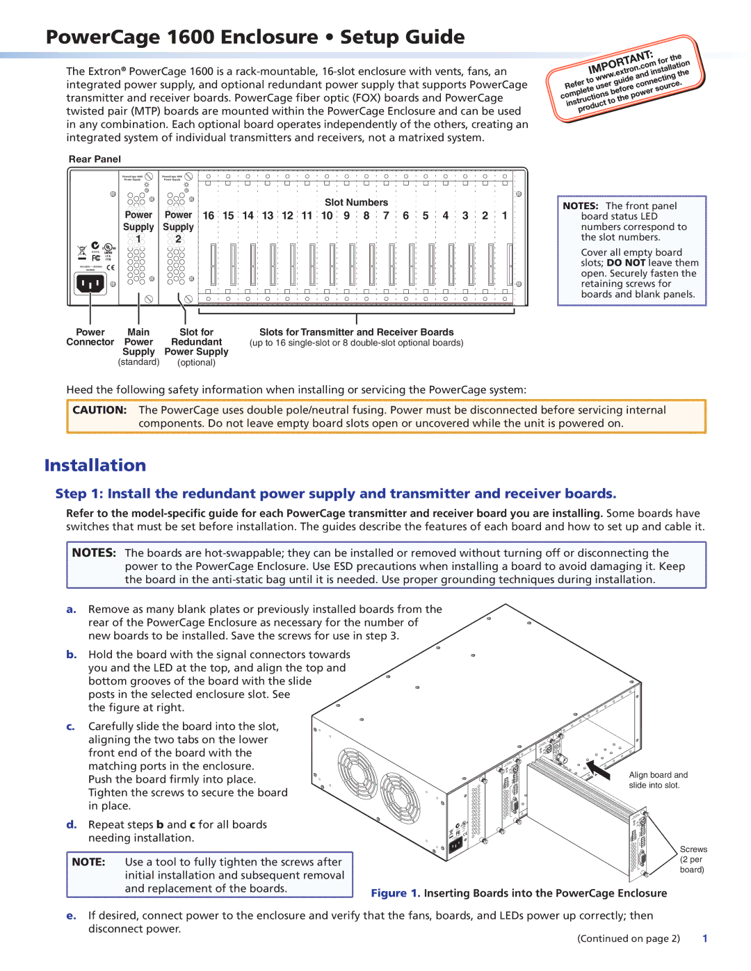
a.Remove as many blank plates or previously installed boards from the
rear of the PowerCage Enclosure as necessary for the number of new boards to be installed. Save the screws for use in step 3.
b.Hold the board with the signal connectors towards you and the LED at the top, and align the top and bottom grooves of the board with the slide
posts in the selected enclosure slot. See the figure at right.
c. Carefully slide the board into the slot, aligning the two tabs on the lower front end of the board with the matching ports in the enclosure. Push the board firmly into place. Tighten the screws to secure the board in place.
d.Repeat steps b and c for all boards needing installation.
![]() NOTE: Use a tool to fully tighten the screws after
NOTE: Use a tool to fully tighten the screws after ![]() initial installation and subsequent removal
initial installation and subsequent removal
N15778
C
INPUT
![]() Tx Rx
Tx Rx![]()
C
| Tx Rx | ALARM | 1 2 |
FIBER |
| TxRx | |
TxRx | REMOTE | ||
R |
| ||
OVER | AUDIO L |
|
OUTPUT | RGB |
US
LISTED 1T23..E I.T
Align board and slide into slot.
| Tx Rx | ALARM | 1 2 |
|
FIBER |
| TxRx |
| |
TxRx | REMOTE |
| ||
R |
|
| ||
OVER | AUDIO L |
| Screws | |
| OUTPUT |
| RGB | |
|
| (2 per | ||
|
|
|
| |
|
|
|
| board) |
and replacement of the boards.
Figure 1. Inserting Boards into the PowerCage Enclosure
e. If desired, connect power to the enclosure and verify that the fans, boards, and LEDs power up correctly; then
disconnect power. | 1 |
(Continued on page 2) |