DTP DVI 230 D and HDMI 230/330 D • Setup Guide
This setup guide provides instructions for an experienced installer to set up and operate the Extron DTP DVI 230 D and DTP HDMI 230 and 330 D extenders.
INPUTS |
| LOCAL OUT |
|
DDC |
|
|
|
|
ROUTE |
|
|
|
|
REMOTE |
|
| |
|
ON | IR |
| ||
AUDIO |
|
|
| |
1 2 |
|
| | |
LOCAL | Tx Rx G Tx Rx |
| ||
|
|
| ||
INPUTS
AUDIO ![]()
OVER DTP
IR | |
Tx Rx G Tx Rx | |
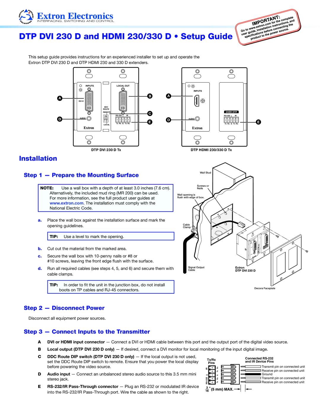
DTP DVI 230 D Tx
Installation
DTP HDMI 230/330 D Tx
Step 1 — Prepare the Mounting Surface
NOTE: Use a wall box with a depth of at least 3.0 inches (7.6 cm). Alternatively, the included mud ring (MR 200) can be used.
For more information, see the full product user guides at www.extron.com. The installation must comply with the National Electric Code.
a.Place the wall box against the installation surface and mark the opening guidelines.
TIP: Use a level to mark the opening.
b.Cut out the material from the marked area.
c.Secure the wall box with
#10 screws, leaving the front edge flush with the surface.
d.Run all required cables (see steps 4, 5, and 6) and secure them with cable clamps.
Wall Stud
Screws or
Nails
Wall opening is
flush with edge of box.
Cable
Clamp ![]()
![]()
INPUTS |
| DVI | |
|
| |
|
| O |
| AUDI | |
Signal Output | Extron |
|
Cable | DTP DVI 230 D | |
OUT
LOCAL |
RS- | 232 |
|
|
|
| Tx | Rx |
| G |
| |
TxRx |
|
| |
TIP: In order to fit the unit in the junction box, do not install boots on TP cables and
Decora Faceplate
Step 2 — Disconnect Power
Disconnect all equipment power sources.
Step 3 — Connect Inputs to the Transmitter
ADVI or HDMI input connector — Connect a DVI or HDMI cable between this port and the output port of the digital video source.
BLocal output (DTP DVI 230 D only) — If desired, connect a DVI monitor for local monitoring of the input digital image.
C | DDC Route DIP switch (DTP DVI 230 D only) — If the local output is not used, | Tx/Rx |
| Connected |
| set the DDC Route DIP switch to remote. Ensure that you power the local display |
| and IR Device Pins | |
| Pins |
| ||
| before powering the video source. | IR | Rx | Transmit pin on connected unit |
|
| Receive pin on connected unit | ||
D | Audio input — Connect an unbalanced stereo audio source to this 3.5 mm mini |
| G Tx | |
| Ground | |||
| stereo jack. | 232 | Rx | Transmit pin on connected unit |
E | RS- | Tx | Receive pin on connected unit | |
|
|
|
into the