Step 4 — Run Cables Between Units
NOTES:
•The DTP DVI/HDMI 230 D models can transmit video, control, and audio (if applicable) signals up to 230 feet (70m).
•The DTP HDMI 330 D model can transmit video, control, and audio (if applicable) signals up to 330 feet (100m).
Connect the rear panel transmitter output to the rear panel receiver input using shielded twisted pair (STP) cable. For optimal performance, Extron highly recommends the following:
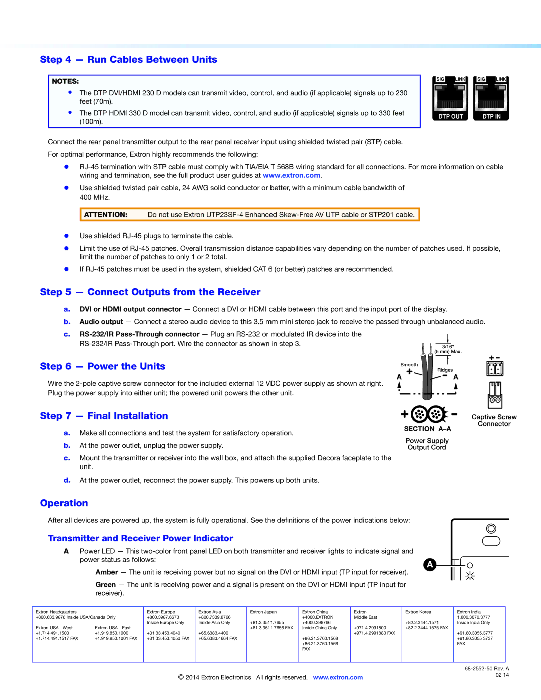
SIG ![]() LINK SIG
LINK SIG ![]() LINK
LINK
DTP OUT | DTP IN |
zz
zz Use shielded twisted pair cable, 24 AWG solid conductor or better, with a minimum cable bandwidth of 400 MHz.
ATTENTION: Do not use Extron
zz Use shielded
zz Limit the use of
zz If
Step 5 — Connect Outputs from the Receiver
a.DVI or HDMI output connector — Connect a DVI or HDMI cable between this port and the input port of the display.
b.Audio output — Connect a stereo audio device to this 3.5 mm mini stereo jack to receive the passed through unbalanced audio.
c.
Step 6 — Power the Units
Wire the
| 3/16" |
| (5 mm) Max. |
Smooth | Ridges |
| |
A | A |
Step 7 — Final Installation
a.Make all connections and test the system for satisfactory operation.
b.At the power outlet, unplug the power supply.
c.Mount the transmitter or receiver into the wall box, and attach the supplied Decora faceplate to the unit.
d.At the power outlet, reconnect the power supply. This powers up both units.
SECTION
Power Supply
Output Cord
Captive Screw
Connector
Operation
After all devices are powered up, the system is fully operational. See the definitions of the power indications below:
Transmitter and Receiver Power Indicator
A | Power LED — This |
|
|
|
| ||||||
| power status as follows: |
|
|
|
|
| A |
|
|
| |
| Amber — The unit is receiving power but no signal on the DVI or HDMI input (TP input for receiver). |
|
|
| |||||||
|
|
|
| ||||||||
| Green — The unit is receiving power and a signal is present on the DVI or HDMI input (TP input for |
|
|
|
| ||||||
| receiver). |
|
|
|
|
|
|
|
|
|
|
|
|
|
|
|
|
|
|
|
|
| |
Extron Headquarters |
| Extron Europe | Extron Asia | Extron Japan | Extron China | Extron | Extron Korea | Extron India | |||
+800.633.9876 Inside USA/Canada Only | +800.3987.6673 | +800.7339.8766 |
| +4000.EXTRON | Middle East |
|
|
| 1.800.3070.3777 | ||
|
| Inside Europe Only | Inside Asia Only | +81.3.3511.7655 | +4000.398766 |
| +82.2.3444.1571 | Inside India Only | |||
Extron USA - West | Extron USA - East |
|
| +81.3.3511.7656 FAX | Inside China Only | +971.4.2991800 | +82.2.3444.1575 FAX |
|
| ||
+1.714.491.1500 | +1.919.850.1000 | +31.33.453.4040 | +65.6383.4400 |
|
| +971.4.2991880 FAX |
|
|
| +91.80.3055.3777 | |
+1.714.491.1517 FAX | +1.919.850.1001 FAX | +31.33.453.4050 FAX | +65.6383.4664 FAX |
| +86.21.3760.1568 |
|
|
|
| +91.80.3055 3737 | |
|
|
|
|
| +86.21.3760.1566 |
|
|
|
| FAX | |
|
|
|
|
| FAX |
|
|
|
|
|
|
|
|
|
|
|
|
|
|
|
|
|
|
| |
© 2014 Extron Electronics All rights reserved. www.extron.com | 02 14 |