32
VN-Matrix 200 • Setup Guide, cont’d
c Network connectors (I and II) — Two female RJ-45 connectors are used to connect the VN-Matrix 200 to an Ethernet network.
Typically, port I is used for data streaming and device configuration (using the Web interface). Port II is reserved for future use and
special applications.
d Peripheral keyboard connector — Connect the keyboard to the PS/2 port.
e Peripheral mouse connector — Connect the mouse to the PS/2 port.
f PC keyboard connector — Connect the VN-Matrix 200 PS/2 keyboard port to the PS/2 keyboard port of the PC.
g PC mouse connector — Connect the VN-Matrix 200 PS/2 mouse port to the PS/2 mouse port of the PC.
h DVI-I output connector — Connect the computer monitor to this female DVI-I output port.
i DVI-I input connector — Connect the DVI-I output port of the computer to this female DVI-I input port.
j COM 1 serial input-output connector — This male 9-pin port is used to configure the VN-Matrix 200. Connect it to RS-232 (com) port
of the PC.
k COM 2 serial input-output connector — This male 9-pin port is used to transmit and receive data across a network.

Initial Setup

1. Connect the PC to the 9-pin COM 1 port j of the VN-Matrix 200.
2. To initiate communication between the computer and the VN-Matrix 200, run HyperTerminal from the PC. Set the
communications settings as shown below.
3. Connect the power supply to the VN-Matrix 200 a.
4. After receiving the following “login:” prompt, type config then press the <Enter> key.
VN Matrix (R) Maintenance Console: ver3.3c
192.168.0.1 login:
Password:

When prompted for Password:, type config then press the <Enter> key. The option menu is displayed.
5. Change the settings as needed by typing the option number then pressing the <Enter> key. Next, type in the new
setting and press the <Enter> key.
NOTE: Do not include any extra zeros when typing in IP addresses. For example, type 192.168.0.18; do not type
192.168.000.018.
Once all the changes have been made, type 9 and press the <Enter> key to exit the menu. The VN-Matrix 200 will
automatically reboot to implement the new settings.
6. Reboot each VN-Matrix 200 once it is connected to the network by inserting
a very small screwdriver or straightened paperclip into the small hole on the
front panel just to the left of the LED indicators as shown at right.
7. A typical VN-Matrix network includes an Encoder (PC input), a Decoder (display output), and a PC (control). See the
following example connection diagram and explanations.
12V DC
REG
6A MAX I
IN
OUT
DIGITAL
AUDIO II
COM 1
OUT
PCPERIPH IN
COM 2
DVI-IDVI-I
VN-Matrix
Encoder
VN-Matrix
Decoder
12V DC
REG
6A MAX I
IN
OUT
DIGITAL
AUDIO II
COM 1
OUT
PCPERIPH IN
COM 2
DVI-IDVI-I å
ç
K
TCP/IP
Network
Control PC (web browser control)
Display
PC (video source)
Local Monitor Display (optional)
IP Address:
192.168.0.101
IP Address:
192.168.0.102
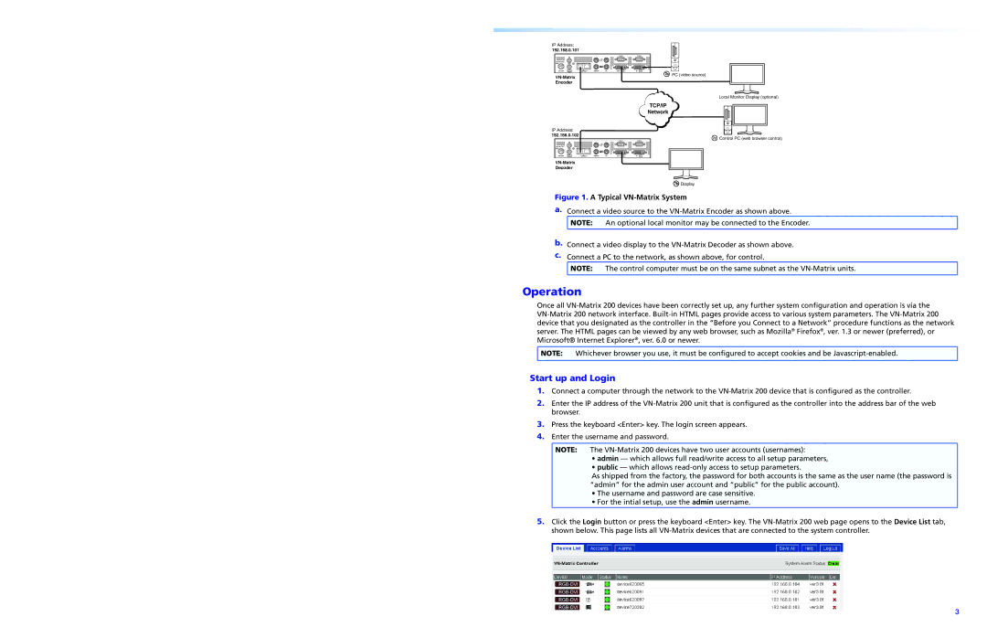
Figure 1. A Typical VN-Matrix System
a. Connect a video source to the VN-Matrix Encoder as shown above.
NOTE: An optional local monitor may be connected to the Encoder.
b. Connect a video display to the VN-Matrix Decoder as shown above.
c. Connect a PC to the network, as shown above, for control.
NOTE: The control computer must be on the same subnet as the VN-Matrix units.

Operation

Once all VN-Matrix 200 devices have been correctly set up, any further system configuration and operation is via the
VN-Matrix 200 network interface. Built-in HTML pages provide access to various system parameters. The VN-Matrix 200
device that you designated as the controller in the “Before you Connect to a Network” procedure functions as the network
server. The HTML pages can be viewed by any web browser, such as Mozilla® Firefox®, ver. 1.3 or newer (preferred), or
Microsoft® Internet Explorer®, ver. 6.0 or newer.
NOTE: Whichever browser you use, it must be configured to accept cookies and be Javascript-enabled.
Start up and Login
1. Connect a computer through the network to the VN-Matrix 200 device that is configured as the controller.
2. Enter the IP address of the VN-Matrix 200 unit that is configured as the controller into the address bar of the web
browser.
3. Press the keyboard <Enter> key. The login screen appears.
4. Enter the username and password.
NOTE: The VN-Matrix 200 devices have two user accounts (usernames):
admin — which allows full read/write access to all setup parameters,
public — which allows read-only access to setup parameters.
As shipped from the factory, the password for both accounts is the same as the user name (the password is
“admin” for the admin user account and “public” for the public account).
• The username and password are case sensitive.
• For the intial setup, use the admin username.
5. Click the Login button or press the keyboard <Enter> key. The VN-Matrix 200 web page opens to the Device List tab,
shown below. This page lists all VN-Matrix devices that are connected to the system controller.
VN-MATRIX 200 SERIES
RGB/DVI OVER IP
LAN-1
LAN-2
STATUS
Reset Hole