1
4
68-1921-50
Rev. A
10 10
Extron USA - West
Headquarters
+800.633.9876
Inside USA/Canada
Only
+1.714.491.1500
+1.714.491.1517 FAX
Extron USA - East
+800.633.9876
Inside USA/Canada
Only
+1.919.863.1794
+1.919.863.1797 FAX
Extron Europe
+800.3987.6673
Inside Europe Only
+31.33.453.4040
+31.33.453.4050 FAX
Extron Asia
+800.7339.8766
Inside Asia Only
+65.6383.4400
+65.6383.4664 FAX
Extron Japan
+81.3.3511.7655
+81.3.3511.7656 FAX
Extron China
+400.833.1568
Inside China Only
+86.21.3760.1568
+86.21.3760.1566 FAX
Extron Middle East
+971.4.2991800
+971.4.2991880 FAX
© 2010 Extron Electronics. All rights reserved. www.extron.com
VN-Matrix 200 • Setup Guide, cont’d VN-Matrix 200 • Setup Guide
The Extron® VN-Matrix 200 Series provides real-time transmission of high resolution audio visual
content across standard IP networks for live viewing, collaboration, storage, and playback.
The VN-Matrix 200 Series encodes video or graphics sources at resolutions up to HD or
WUXGA, streams the video and audio over an IP network, then decodes the
content back to the original source resolution. VN-Matrix applies the Extron
PURE3 Codec, a unique wavelet-based compression technology. The
VN-Matrix 200 Series offers real-time streaming and low latency, making it
ideal for remote collaborative and interactive or control applications. It can be
deployed in live event streaming and high level conferencing for specialized projects.
NOTE: For full installation, configuration, and operation details, refer to the VN-Matrix 200 User Guide, available at
www.extron.com.

Before You Connect to a Network

Before connecting each VN-Matrix to a network you must change its default network settings. On an existing network,
check with the network administrator for a range of suitable IP addresses.
On a closed network, used exclusively by VN-Matrix, we recommend that you use addresses in the range 192.168.0.1 to
192.168.0.254 with a subnet mask of 255.255.255.0. The following diagram shows an example addressing scheme for a
simple system comprising four VN-Matrix units:
RGB/DVI OVER IP
VN-MATRIX 200 SERIES
RGB/DVI OVER IP
VN-MATRIX 200 SERIES
RGB/DVI OVER IP
LAN-1
LAN-2
STATUS
VN-MATRIX 200 SERIES
RGB/DVI OVER IP
LAN-1
LAN-2
STATUS
VN-MATRIX 200 SERIES
RGB/DVI OVER IP
LAN-1
LAN-2
STATUS
VN-MATRIX 200 SERIES
RGB/DVI OVER IP
LAN-1
LAN-2
STATUS
TCP/IPNetwork
Controller
IP Address: 192.168.0.101
Subnet mask: 255.255.255.0
IP Address: 192.168.0.102
Subnet mask: 255.255.255.0
IP Address: 192.168.0.104
Subnet mask: 255.255.255.0
IP Address: 192.168.0.103
Subnet mask: 255.255.255.0
VN-Matrix Controller
One VN-Matrix device in a group must be designated as the “controller.” All system configuration is achieved via a web
interface that is served up by the controller. In the above example, the unit at address 192.168.0.101 is designated the
controller for this group of VN-Matrix devices. Note that the controller IP value on each device is set to this address.
Setup Procedure
Follow the step-by-step instructions in the “Initial Setup” section for each VN-Matrix, then follow the “Operation
section instructions to create a simple VN-Matrix system. For more detailed information and advanced setup procedures
refer to the user guide.

Rear Panel Features

12V DC
REG
6A MAXI
IN
OUT
DIGITAL
AUDIO II
COM 1
OUT
PCPERIPH IN
COM 2
DVI-IDVI-I
ab
eg jk
cdfh i
a DC power connector — The VN-Matrix 200 requires a 12 VDC regulated power supply (rated at 6 A) via this connector. A suitable
power supply unit (PSU) is provided.
b Digital audio connectors — Use these two female RCA connectors for input or output digital audio signals through S/PDIF coaxial
cables.

Congure the VN-Matrix 200 Units as Encoders or Decoders

The Mode column on the Device List tab shows how each VN-Matrix 200 unit is configured using the following icons:
= Encoder = Decoder = Recorder or a playback device = Undefined
NOTE: The VN-Matrix Recorder is not documented here. The device list may show more devices than are in your
system. This is because the controller maintains a list of devices that have been used previously, but may not be
currently available. In this case, the IP address entry for that device is blank.
Configure the device as an encoder or decoder as follows:
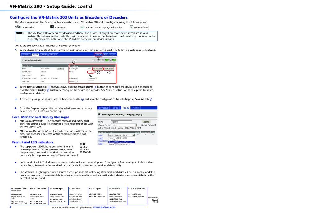
1. In the device list double-click any of the list entries for a device to be configured. The following web page is displayed.
2. In the Device Setup box a shown above, click the create source b button to configure the device as an encoder or
click the create display c button to configure the device as a decoder. See “Device Setup” on the Help tab for more
configuration details.
3. After configuring the device, set the Mode to enable d and save the configuration by selecting the Save All tab e.
4. From the Display page of the decoder select an encoder source
device. See the illustraion on the right.
Local Monitor and Display Messages
zz “No Source Present” An encoder message indicating that
either no source device is connected or it is not compatible with
the VN-Matrix 200.
zz “No Source Datastream” A decoder message indicating that
either no encoder is selected or the chosen encoder is not
streaming.
Front Panel LED indicators
zz The top power LED lights green when the unit
receives power; it flashes green when an over
temperature, overload, or underload condition
occurs. Cycle the power on and off to reset the unit.
zz LAN-1 and LAN-2 LEDs indicate the status of the indicated network ports. They light or flash orange to indicate that
data is being transmitted or received; an unlit state indicates no network or data activity.
zz The Status LED lights green when source data is present but not being streamed (unit disabled or in standby mode); it
flashes green when the source data is being streamed and received; an unlit state indicates that source data is neither
detected nor received.
LAN-1
LAN-2
STATUS