1/4” (0.6 cm) of insulation from each wire. Do not solder the tips. Insert each wire into the correct position on the captive screw connector, and tighten each screw. See the diagrams below.
To pass through an IR signal that includes a carrier signal, connect the signal wire to the pin designated for carrier and signal.
If you want the IR Broadcaster to generate the carrier signal, connect the signal wire to the pin designated for signal only.
COMM |
A |
B |
C |
D |
E |
System 5
Comm port
Signal only
Gnd | Sleeve (Gnd) | Tip (+12V) |
Carrier & signal |
| To the |
Gnd |
| |
| IR Broadcaster | |
+12V |
| |
| ||
| Ring (Signal) | |
|
| |
| Tip (+12V) |
|
| Sleeve (Gnd) |
|
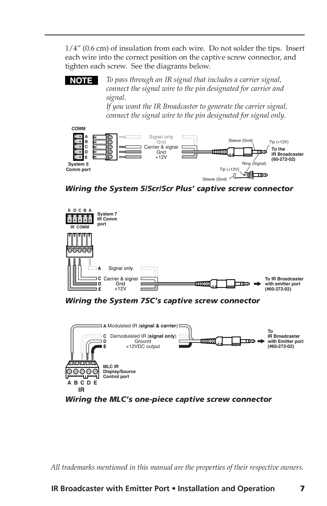
Wiring the System 5/5cr/5cr Plus’ captive screw connector
E D C B A
IR COMM
System 7 IR Comm port
![]() A Signal only
A Signal only
![]() C Carrier & signal
C Carrier & signal
D | Gnd |
E | +12V |
To IR Broadcaster with emitter port
Wiring the System 7SC’s captive screw connector
A Modulated IR (signal & carrier)
CDemodulated IR (signal only)
D | Ground |
E | +12VDC output |
To
IR Broadcaster with Emitter port
A B C D E |
IR
MLC IR Display/Source Control port
Wiring the MLC’s one-piece captive screw connector
All trademarks mentioned in this manual are the properties of their respective owners.
IR Broadcaster with Emitter Port • Installation and Operation | 7 |