Installation and Operation
Wiring tip-ring-sleeve and tip-sleeve connectors
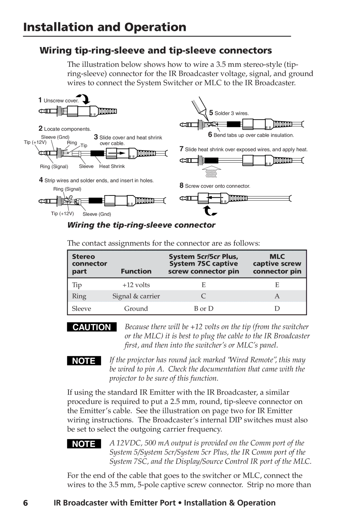
The illustration below shows how to wire a 3.5 mm
1Unscrew cover. ![]()
2 Locate components. | 3 Slide cover and heat shrink | ||
Sleeve (Gnd) |
| ||
Tip (+12V) | Ring | Tip | over cable. |
| |||
Ring (Signal) | Sleeve | Heat Shrink | |
4 Strip wires and solder ends, and insert in holes. | |||
| Ring (Signal) |
| |
| Tip (+12V) | Sleeve (Gnd) | |
5 Solder 3 wires.
6 Bend tabs up over cable insulation.
7 Slide heat shrink over exposed wires, and apply heat.
8 Screw cover onto connector.
Wiring the tip-ring-sleeve connector
The contact assignments for the connector are as follows:
Stereo |
| System 5cr/5cr Plus, | MLC |
connector |
| System 7SC captive | captive screw |
part | Function | screw connector pin | connector pin |
Tip | +12 volts | E | E |
|
|
|
|
Ring | Signal & carrier | C | A |
Sleeve | Ground | B or D | D |
|
|
|
|
CAUTION
Because there will be +12 volts on the tip (from the switcher or the MLC) it is best to plug the cable to the IR Broadcaster first, and then into the switcher’s or MLC’s panel.
If the projector has round jack marked “Wired Remote”, this may be wired to pin A. Check the documentation that came with the projector to be sure of this function.
If using the standard IR Emitter with the IR Broadcaster, a similar procedure is required to put a 2.5 mm, round,
A 12VDC, 500 mA output is provided on the Comm port of the System 5/System 5cr/System 5cr Plus, the IR Comm port of the System 7SC, and the Display/Source Control IR port of the MLC.
For the end of the cable that goes to the switcher or MLC, connect the wires to the 3.5 mm,
6IR Broadcaster with Emitter Port • Installation & Operation