Digital Signal Conditioning
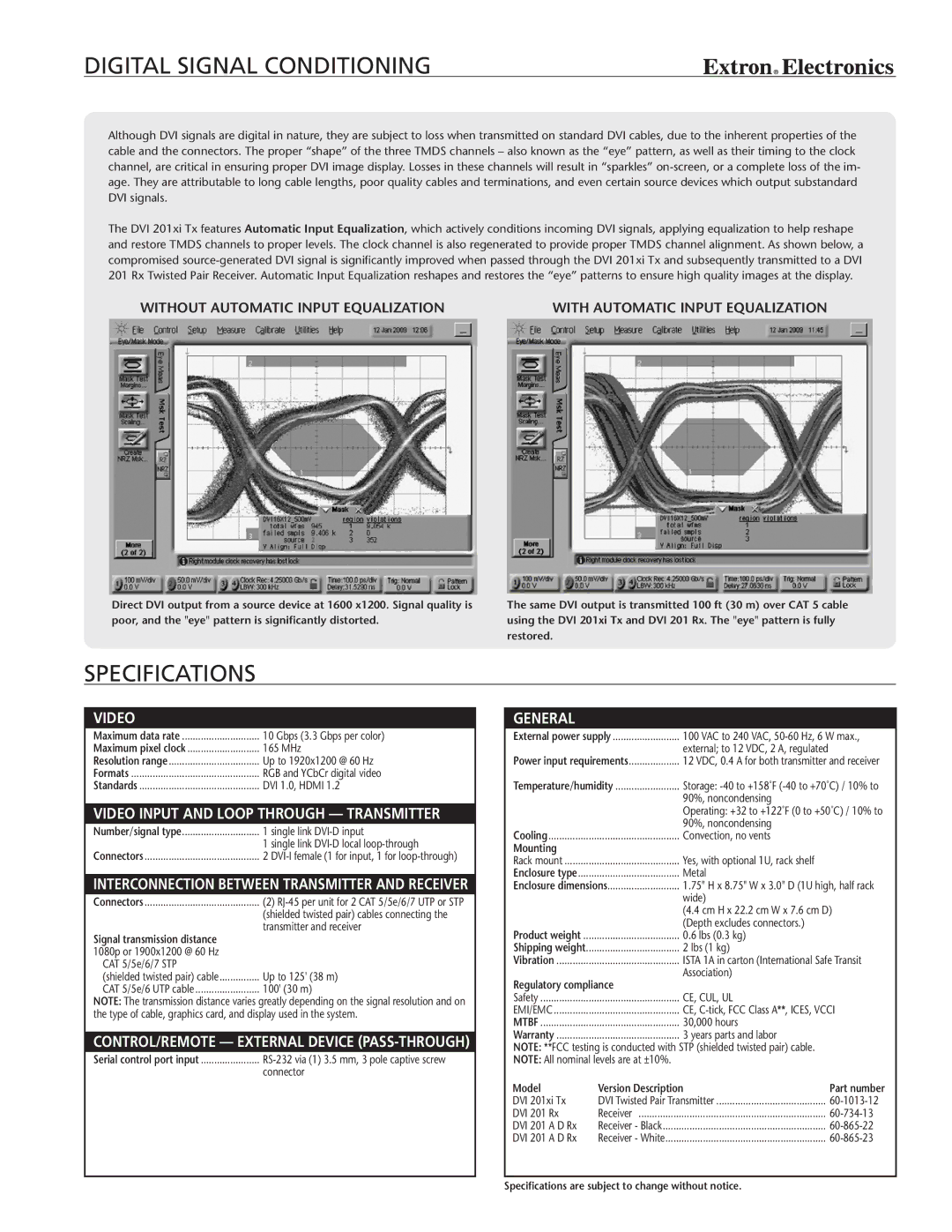
Although DVI signals are digital in nature, they are subject to loss when transmitted on standard DVI cables, due to the inherent properties of the cable and the connectors. The proper “shape” of the three TMDS channels – also known as the “eye” pattern, as well as their timing to the clock channel, are critical in ensuring proper DVI image display. Losses in these channels will result in “sparkles”
The DVI 201xi Tx features Automatic Input Equalization, which actively conditions incoming DVI signals, applying equalization to help reshape and restore TMDS channels to proper levels. The clock channel is also regenerated to provide proper TMDS channel alignment. As shown below, a compromised
Without Automatic Input Equalization | With Automatic Input Equalization |
Direct DVI output from a source device at 1600 x1200. Signal quality is poor, and the "eye" pattern is significantly distorted.
The same DVI output is transmitted 100 ft (30 m) over CAT 5 cable using the DVI 201xi Tx and DVI 201 Rx. The "eye" pattern is fully restored.
specifications
Video
Maximum data rate | .10 Gbps (3.3 Gbps per color) |
Maximum pixel clock | .165 MHz |
Resolution range | .Up to 1920x1200 @ 60 Hz |
Formats | .RGB and YCbCr digital video |
Standards | .DVI 1.0, HDMI 1.2 |
Video input and loop through — transmitter
Number/signal type | .1 single link |
Connectors | 1 single link |
.2 |
Interconnection between transmitter and receiver
Connectors | .(2) |
| (shielded twisted pair) cables connecting the |
Signal transmission distance | transmitter and receiver |
| |
1080p or 1900x1200 @ 60 Hz |
|
CAT 5/5e/6/7 STP |
|
(shielded twisted pair) cable | .Up to 125' (38 m) |
CAT 5/5e/6 UTP cable | .100' (30 m) |
NOTE: The transmission distance varies greatly depending on the signal resolution and on the type of cable, graphics card, and display used in the system.
Control/remote — external device
Serial control port input | |
| connector |
General
External power supply | .100 VAC to 240 VAC, | ||
Power input requirements | external; to 12 VDC, 2 A, regulated |
| |
.12 VDC, 0.4 A for both transmitter and receiver | |||
Temperature/humidity | .Storage: | ||
|
| 90%, noncondensing |
|
|
| Operating: +32 to +122˚F (0 to +50˚C) / 10% to | |
Cooling | 90%, noncondensing |
| |
.Convection, no vents |
| ||
Mounting |
|
|
|
Rack mount | .Yes, with optional 1U, rack shelf |
| |
Enclosure type | .Metal |
| |
Enclosure dimensions | .1.75" H x 8.75" W x 3.0" D (1U high, half rack | ||
|
| wide) |
|
|
| (4.4 cm H x 22.2 cm W x 7.6 cm D) | |
Product weight | (Depth excludes connectors.) |
| |
.0.6 lbs (0.3 kg) |
| ||
Shipping weight | .2 lbs (1 kg) |
| |
Vibration | .ISTA 1A in carton (International Safe Transit | ||
Regulatory compliance | Association) |
| |
|
| ||
Safety | .CE, CUL, UL |
| |
EMI/EMC | .CE, | ||
MTBF | .30,000 hours |
| |
Warranty | .3 years parts and labor |
| |
NOTE: **FCC testing is conducted with STP (shielded twisted pair) cable. |
| ||
NOTE: All nominal levels are at ±10%. |
|
| |
Model | Version Description | Part number | |
DVI 201xi Tx | DVI Twisted Pair Transmitter | ||
DVI 201 Rx | Receiver | ||
DVI 201 A D Rx | Receiver - Black | ||
DVI 201 A D Rx | Receiver - White | ||
Specifications are subject to change without notice.
