FF220T Setup Guide (Continued)
c.Strip 3/16” (5 mm) from the wire ends and keep the wire end strands together by twisting them. Do not tin the wires.
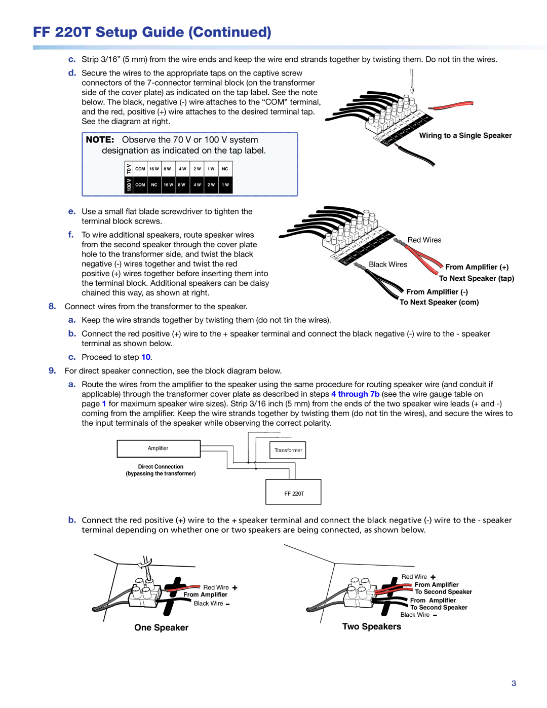
d.Secure the wires to the appropriate taps on the captive screw
connectors of the |
|
|
| |
side of the cover plate) as indicated on the tap label. See the note |
|
|
| |
below. The black, negative |
|
|
| |
and the red, positive (+) wire attaches to the desired terminal tap. |
| W | NC | |
See the diagram at right. | W | 1W | ||
1 | ||||
| W |
| 2W | |
| 2 |
| ||
| 4 | 4W |
|
NOTE: Observe the 70 V or 100 V system | ||||||||
designation as indicated on the tap label. | ||||||||
V | COM | 16 W | 8 W | 4 W | 2 W | 1 W | NC | |
70 | ||||||||
|
|
|
|
|
|
| ||
V |
|
|
|
|
|
|
| |
100 | COM | NC | 16 W | 8 W | 4 W | 2 W | 1 W | |
|
|
|
|
|
|
| ||
V
COM 70 V
W | 8W |
8 | |
W | W |
16 | 16 |
NC |
|
COM |
|
100 |
|
Wiring to a Single Speaker
e.Use a small flat blade screwdriver to tighten the terminal block screws.
f. To wire additional speakers, route speaker wires from the second speaker through the cover plate hole to the transformer side, and twist the black negative
8.Connect wires from the transformer to the speaker.
a. Keep the wire strands together by twisting them (do not tin the wires).
V
COM 70 V
8W 16W
NC COM 100 ![]()
|
| NC |
|
|
| W |
| 1W |
|
4W | 1 |
| Red Wires | |
4W |
|
| ||
| W | 2W |
|
|
| 2 |
|
| |
| 8W |
|
|
|
W |
|
|
|
|
16 |
|
|
|
|
Black Wires | From Amplifier (+) |
| |
| To Next Speaker (tap) |
From Amplifier (-)
To Next Speaker (com)
b.Connect the red positive (+) wire to the + speaker terminal and connect the black negative
c.Proceed to step 10.
9.For direct speaker connection, see the block diagram below.
a.Route the wires from the amplifier to the speaker using the same procedure for routing speaker wire (and conduit if applicable) through the transformer cover plate as described in steps 4 through 7b (see the wire gauge table on page 1 for maximum speaker wire sizes). Strip 3/16 inch (5 mm) from the ends of the two speaker wire leads (+ and
Amplifier
Direct Connection
(bypassing the transformer)
Transformer
FF 220T
b.Connect the red positive (+) wire to the + speaker terminal and connect the black negative
| Red Wire | |
Red Wire | From Amplifier | |
To Second Speaker | ||
From Amplifier | ||
From Amplifier | ||
Black Wire | ||
To Second Speaker | ||
| ||
| Black Wire | |
One Speaker | Two Speakers |
3