OnSite Series Getting Started Guide | 3 • Installation Overview |
|
|
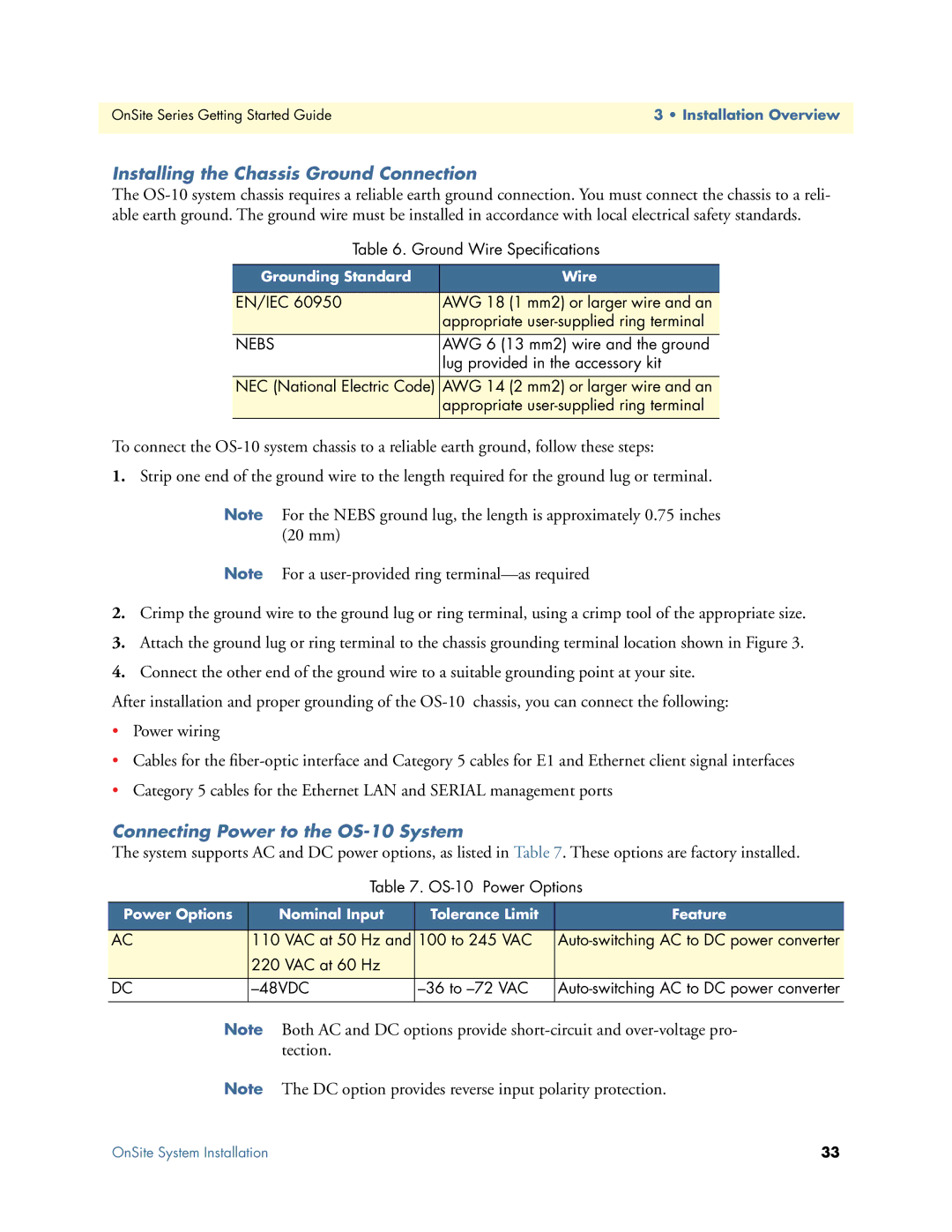
Installing the Chassis Ground Connection
The
Table 6. Ground Wire Specifications
Grounding Standard | Wire |
|
|
EN/IEC 60950 | AWG 18 (1 mm2) or larger wire and an |
| appropriate |
|
|
NEBS | AWG 6 (13 mm2) wire and the ground |
| lug provided in the accessory kit |
|
|
NEC (National Electric Code) | AWG 14 (2 mm2) or larger wire and an |
| appropriate |
|
|
To connect the
1.Strip one end of the ground wire to the length required for the ground lug or terminal.
Note For the NEBS ground lug, the length is approximately 0.75 inches (20 mm)
Note For a
2.Crimp the ground wire to the ground lug or ring terminal, using a crimp tool of the appropriate size.
3.Attach the ground lug or ring terminal to the chassis grounding terminal location shown in Figure 3.
4.Connect the other end of the ground wire to a suitable grounding point at your site.
After installation and proper grounding of the
•Power wiring
•Cables for the
•Category 5 cables for the Ethernet LAN and SERIAL management ports
Connecting Power to the OS-10 System
The system supports AC and DC power options, as listed in Table 7. These options are factory installed.
Table 7.
Power Options | Nominal Input | Tolerance Limit | Feature | |
|
|
|
|
|
AC | 110 VAC at 50 | Hz and | 100 to 245 VAC | |
| 220 VAC at 60 | Hz |
|
|
|
|
|
|
|
DC |
| |||
|
|
|
|
|
Note Both AC and DC options provide
Note The DC option provides reverse input polarity protection.
OnSite System Installation | 33 |