OnSite Series Getting Started Guide | 3 • Installation Overview |
|
|
Mechanical Recommendations for the Rack
The following information will help you plan your equipment rack configuration:
•Use a rack made of steel or aluminum.
•Install equipment in the lower half of the rack first to avoid making the rack top heavy.
•The rack should be able to support the full weight of the final installed chassis.
•Enclosed racks must have adequate ventilation. Ensure that the rack is not overly congested because each unit generates heat. An enclosed rack should have louvered sides and a fan to provide cooling air.
•When mounting a chassis in an open rack, ensure that the rack frame does not block the cooling holes. If the chassis is installed on slides, check the position of the chassis when it is seated all the way into the rack.
•In an enclosed rack with a ventilation fan in the top, excessive heat generated by equipment near the bot- tom of the rack can be drawn upward and into the intake ports of the equipment above it in the rack. In addition, ensure that you provide adequate ventilation for equipment at the bottom of the rack.
•Baffles can help isolate exhaust air from intake air, which also helps draw cooling air through the chassis. The best placement of the baffles depends on the airflow patterns in the rack, which can be found by exper- imenting with different arrangements.
Protective Grounding for the Rack and Chassis
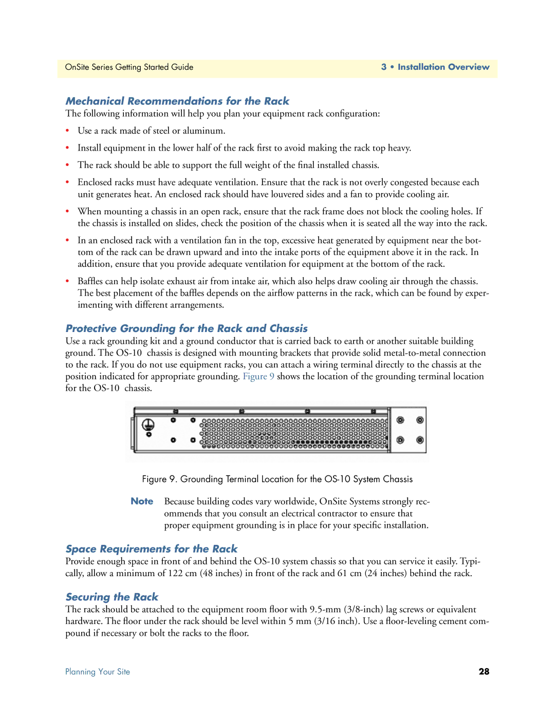
Use a rack grounding kit and a ground conductor that is carried back to earth or another suitable building ground. The
Figure 9. Grounding Terminal Location for the OS-10 System Chassis
Note Because building codes vary worldwide, OnSite Systems strongly rec- ommends that you consult an electrical contractor to ensure that proper equipment grounding is in place for your specific installation.
Space Requirements for the Rack
Provide enough space in front of and behind the
Securing the Rack
The rack should be attached to the equipment room floor with
Planning Your Site | 28 |