OnSite Series Getting Started Guide | 3 • Installation Overview |
|
|
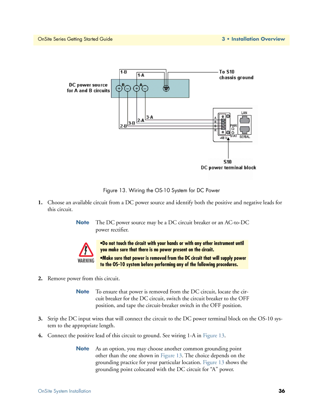
Figure 13. Wiring the OS-10 System for DC Power
1.Choose an available circuit from a DC power source and identify both the positive and negative leads for this circuit.
Note
WARNING
The DC power source may be a DC circuit breaker or an
•Do not touch the circuit with your hands or with any other instrument until you make sure that there is no power present on the circuit.
•Make sure that power is removed from the DC circuit that will supply power to the
2.Remove power from this circuit.
Note To ensure that power is removed from the DC circuit, locate the cir- cuit breaker for the DC circuit, switch the circuit breaker to the OFF position, and tape the
3.Strip the DC input wires that will connect the circuit to the DC power terminal block on the
4.Connect the positive lead of this circuit to ground. See wiring
Note As an option, you may choose another common grounding point other than the one shown in Figure 13. The choice depends on the grounding practice for your particular location. Figure 13 shows the grounding point colocated with the DC circuit for “A” power.
OnSite System Installation | 36 |