OnSite Series Getting Started Guide | 3 • Installation Overview |
|
|
Note The
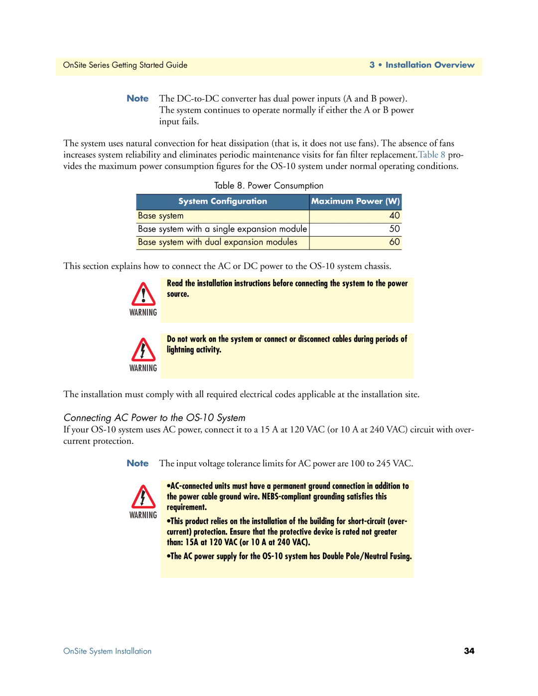
The system uses natural convection for heat dissipation (that is, it does not use fans). The absence of fans increases system reliability and eliminates periodic maintenance visits for fan filter replacement.Table 8 pro- vides the maximum power consumption figures for the
Table 8. Power Consumption
System Configuration | Maximum Power (W) |
|
|
Base system | 40 |
|
|
Base system with a single expansion module | 50 |
|
|
Base system with dual expansion modules | 60 |
|
|
This section explains how to connect the AC or DC power to the
Read the installation instructions before connecting the system to the power source.
WARNING
Do not work on the system or connect or disconnect cables during periods of lightning activity.
WARNING
The installation must comply with all required electrical codes applicable at the installation site.
Connecting AC Power to the OS-10 System
If your
Note
WARNING
The input voltage tolerance limits for AC power are 100 to 245 VAC.
•This product relies on the installation of the building for
•The AC power supply for the
OnSite System Installation | 34 |
