FOX 3G DVC • Setup Guide
The Extron FOX 3G DVC receives fiber optic
![]() NOTE: For full installation, configuration, and operation details, see the FOX 3G DVC User Guide, available at
NOTE: For full installation, configuration, and operation details, see the FOX 3G DVC User Guide, available at
www.extron.com.
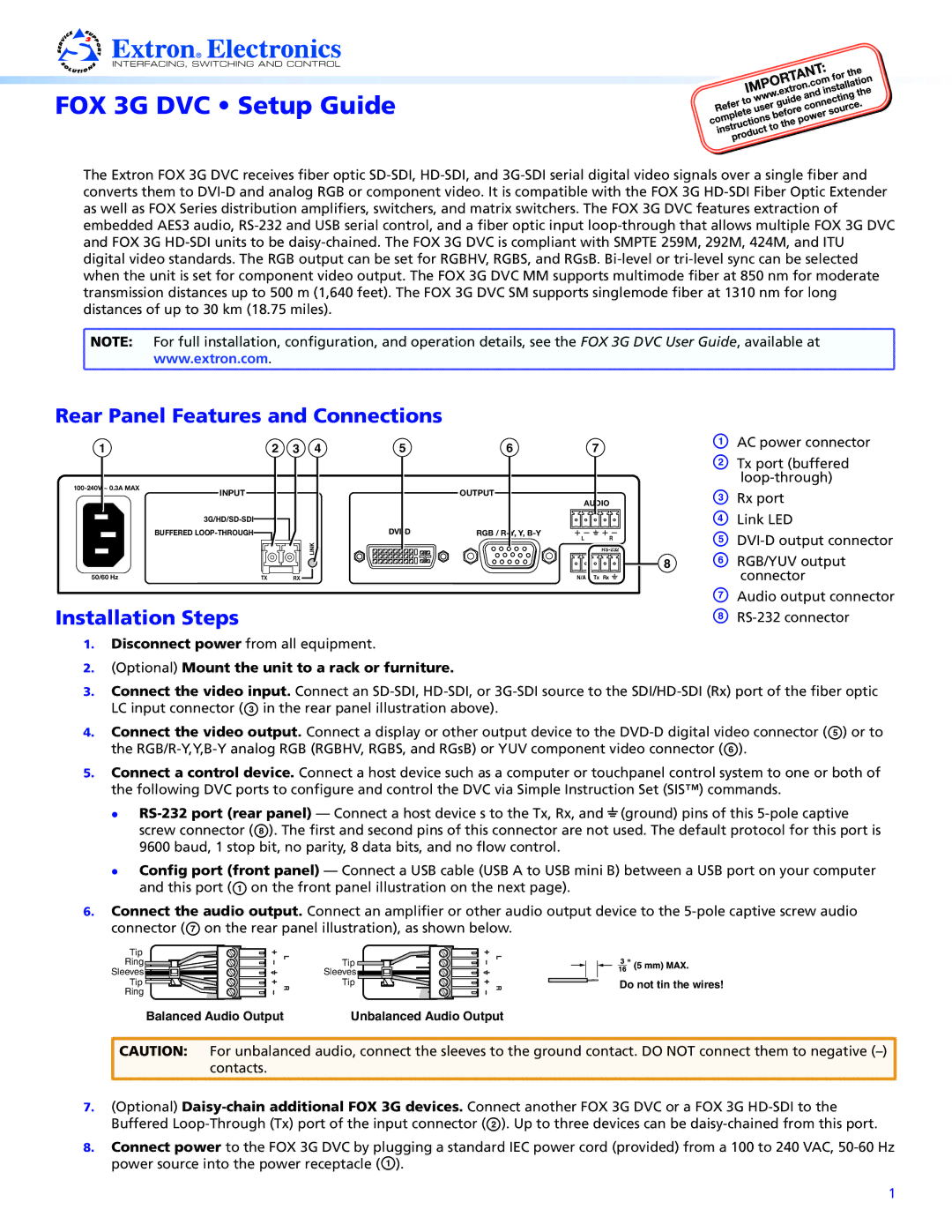
Rear Panel Features and Connections
1 | 2 | 3 |
INPUT |
| |
|
| |
|
| |
| BUFFERED |
|
50/60 Hz | TX | RX |
4 | 5 | 6 | 7 |
| OUTPUT |
|
|
|
| AUDIO | |
RGB / | L | R | |
LINK |
| ||
|
| ||
|
| N/A | Tx Rx |
AAC power connector
BTx port (buffered
CRx port
DLink LED
E
8F RGB/YUV output connector
Installation Steps
GAudio output connector
H
1.Disconnect power from all equipment.
2.(Optional) Mount the unit to a rack or furniture.
3.Connect the video input. Connect an
4.Connect the video output. Connect a display or other output device to the
5.Connect a control device. Connect a host device such as a computer or touchpanel control system to one or both of the following DVC ports to configure and control the DVC via Simple Instruction Set (SIS™) commands.
zz
screw connector (H). The first and second pins of this connector are not used. The default protocol for this port is 9600 baud, 1 stop bit, no parity, 8 data bits, and no flow control.
zz Config port (front panel) — Connect a USB cable (USB A to USB mini B) between a USB port on your computer and this port (A on the front panel illustration on the next page).
6.Connect the audio output. Connect an amplifier or other audio output device to the
Tip |
Ring |
Sleeves |
Tip |
Ring |
L R
Tip
Sleeves ![]()
![]()
![]()
![]()
![]()
![]()
![]()
![]()
Tip
L R
Do not tin the wires!
Balanced Audio Output | Unbalanced Audio Output |
![]() CAUTION: For unbalanced audio, connect the sleeves to the ground contact. DO NOT connect them to negative
CAUTION: For unbalanced audio, connect the sleeves to the ground contact. DO NOT connect them to negative ![]() contacts.
contacts.
7.(Optional)
8.Connect power to the FOX 3G DVC by plugging a standard IEC power cord (provided) from a 100 to 240 VAC,
1