Remote Connector
REMOTE Connector - The Remote connector provides a way to control the VGAxi / MACxi switchers using contact closure devices such as the following:
•Extron
•Third Party Remote Control - Information below may be used to design a third party remote control.
Remote connector pin assignments are shown in the table below (Figure
NOTE __ The duration of a momentary connection is defined as 250 — 500
The Tally pins can be used for remote indication of the switcher's selected input. Tally #1 - #6 (pins 14
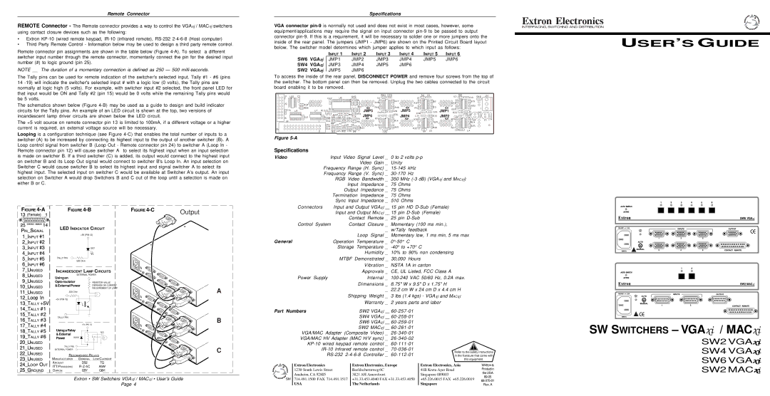
The schematics shown below (Figure
The +5 volt source on remote connector pin 13 is limited to 100mA, if a different voltage or a higher current is required, an external voltage source will be necessary.
Looping is a configuration technique (see Figure
Specifications
VGA connector
|
| INPUT 1 | INPUT 2 | INPUT 3 | INPUT 4 | INPUT 5 | INPUT 6 |
SW6 VGAxi |
| JMP1 | JMP2 | JMP3 | JMP4 | JMP5 | JMP6 |
SW4 VGAxi |
| JMP3 | JMP4 | JMP5 | JMP6 |
|
|
SW2 VGAxi |
| JMP5 | JMP6 |
|
|
|
|
|
|
|
|
|
To access the inside of the rear panel, DISCONNECT POWER and remove four screws from the top of the switcher. The bottom panel can then be removed. Unplug the two cables connected to the circuit board enabling it to be removed.
JMP5 | JMP3 | JMP1 |
JMP6 | JMP4 | JMP2 |
Figure |
|
|
Specifications
Video | Input Video Signal Level _ | 0 to 2 volts | |
| Video Gain _ | Unity | |
| Frequency Range (H. Sync) _ | ||
| Frequency Range (V. Sync) _ | ||
| RGB Video Bandwidth _ | 350 MHz | |
| Input Impedance _ 75 | Ohms | |
| Output Impedance _ | 75 | Ohms |
| Termination Impedance _ | 75 | Ohms |
| Sync Input Impedance _ | 510 Ohms | |
Connectors | Input and Output VGAxi __ 15 | pin HD | |
USER’S GUIDE
FIGURE
FIGURE
LED INDICATOR CIRCUIT
+5V (PIN 13)
LED
TALLY PIN ![]() 330 Ohm
330 Ohm
FIGURE
Output
| Input and Output MACxi __ 15 pin | ||
| Contact Remote _ | 25 pin | |
Control System | Contact Closure _ | Momentary (100 ms min.), | |
|
| _ | w/Tally feedback |
|
| Loop Signal _ | Momentary low, 1 ms min, 5 ms max |
General | Operation | Temperature _ | |
| Storage | Temperature _ | |
|
| Humidity _ | 10% to 90% non condensing |
| MTBF Demonstrated _ 30,000 Hours | ||
|
| Vibration _ | NSTA 1A in carton |
INCANDESCENT LAMP CIRCUITS
EXTERNAL POWER
Using an
| RESISTOR VALUE | ||
& External Power | DEPENDS ON CURRENT | ||
|
| REQUIREMENT OF LAMP | |
| 330 Ohm |
| |
+5V (PIN 13) |
|
| |
TALLY PIN |
|
| |
|
| +5V (PIN 13) | |
Using a Relay | N/C | ||
& External | |||
| |||
Power | 1N916 |
| |
|
| ||
TALLY PIN
EXTERNAL POWER
RECOMMENDED RELAYS
|
| MANUFACTURER | GENERAL | LOW CURRENT | ||||||||||
|
| AROMAT |
| DS2 |
|
| TQ | |||||||
|
| ITT/PANASONIC |
| A5W | ||||||||||
|
|
| ||||||||||||
|
| OMRON |
| G5Y |
| G6H | ||||||||
|
|
|
| |||||||||||
|
|
|
|
|
|
|
|
|
|
|
|
|
|
|
A
B
C
| Approvals _ | CE, UL Listed, FCC Class A |
| ||
Power Supply | Internal _ | ||||
| Dimensions _ | 8.75" W x 9.5" D x 1.75" H |
| ||
| _ | 22.2 cm W x 24 cm D x 4.4 cm H |
| ||
| Shipping Weight _ | 3 lbs (1.4 kgs) - VGAxi and MACxi |
| ||
| Warranty _ | 2 years parts and labor |
| ||
Part Numbers | SW2 VGAxi __ |
|
| ||
| SW4 VGAxi __ |
|
| ||
| SW6 VGAxi __ |
|
| ||
| SW2 MACxi __ |
|
| ||
VGA/MAC Adapter (Composite Video) _ |
|
| |||
VGA/MAC HV Adapter (MAC H/V sync) _ |
|
| |||
|
| ||||
Refer to the safety instructions | |||||
|
|
| |||
in the literature that came with | |||||
|
|
|
| this equipment. | |
Extron Electronics | Extron Electronics, Europe | Extron Electronics, Asia | Written & | ||
1230 South Lewis Street | Beeldschermweg 6C |
| 41B Kreta Ayer Road | Printedin | |
Anaheim, CA 92805 | 3821 AH Amersfoort |
| Singapore 089003 | theUSA | |
| |||||
|
|
|
| ||
SW SWITCHERS – VGA xi / MACxi
SW2 VGAxi
SW4 VGAxi
SW6 VGAxi
SW2 MACxi
Extron • SW Switchers VGAxi / MACxi • User’s Guide
Page 4
SM 714.491.1500 FAX 714.491.1517 | +31.33.453.4040 FAX +31.33.453.4050 | +65.226.0015 FAX +65.226.0019 | ||
USA | The Netherlands | Singapore | ||
Rev. A |