Manuals
/
Extron electronic
/
Computer Equipment
/
Switch
Extron electronic
P/N 68-424-02 Epson Installation, Configuration and Connections, Page
Models:
P/N 68-424-02
1
5
5
Download
5 pages
44.29 Kb
1
2
3
4
5
Config
Page 5
Image 5
Page 4
Page 5
Page 5
Image 5
Page 4
Page 5
Contents
THIS SWITCHER HAS BEEN CONFIGURED FOR EPSON 5300/7300
PLEASE READ THIS DOCUMENT FOR IMPORTANT INSTALLATION INSTRUCTIONS
Kit Type EPSON
SYSTEM PROJECTOR COMMUNICATIONS KIT
Config
Connecting System 4xi to Epson 5300/7300
removed at the AC cord, and then restored
Projector
System 4xi. See page 2-5 for cabling guidelines
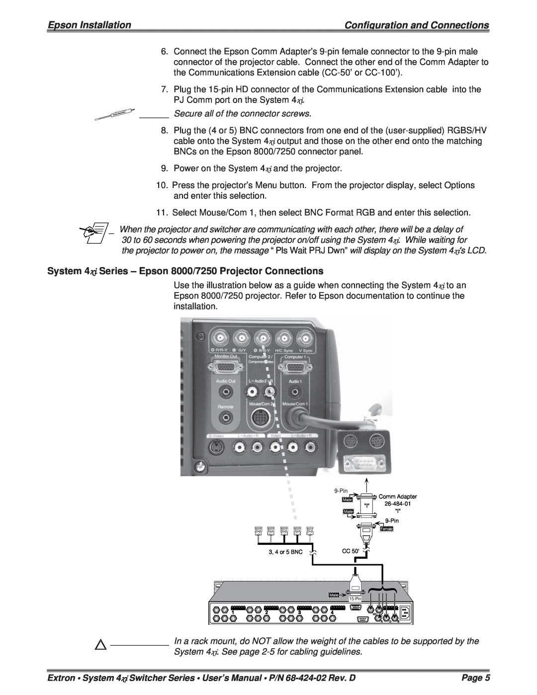
Secure all of the connector screws
System 4xi Series - Epson 5300/7300 Projector Connections
Epson 8000/7250
Connecting System 4xi to Epson 8000/7250
Adapter
System 4xi Series - Epson 8000/7250 Projector Connections
Top
Page
Image
Contents