PMK 550 • Installation Guide
| IMPORTANT: | the | |||||
|
|
|
| .com | for |
| guide, |
| .extron |
|
| . | |||
| towww |
| installation |
| |||
Go | system |
| specifications | ||||
complete | and |
|
|
|
| ||
instructions, |
|
|
|
|
|
| |
The Extron PMK 550 Pole Mount Kit, designed for use with the Extron PoleVault™ System, allows for easy mounting of PoleVault products to a projector pole. The PMK 550 is compatible with both the PVS 204 series and PVS 305 series of PoleVault switchers. When installed it mounts the PoleVault system switcher, the associated power supply, and an accessory device within an enclosure below a suspended ceiling.
CAUTION: Maximum load for the PMK 550 is 15 lbs (6.8 kg).
Items included in the kit are:
Covers (2), Base plate (1), Mounting plate (1), Tie wraps and pads (to secure power supply),
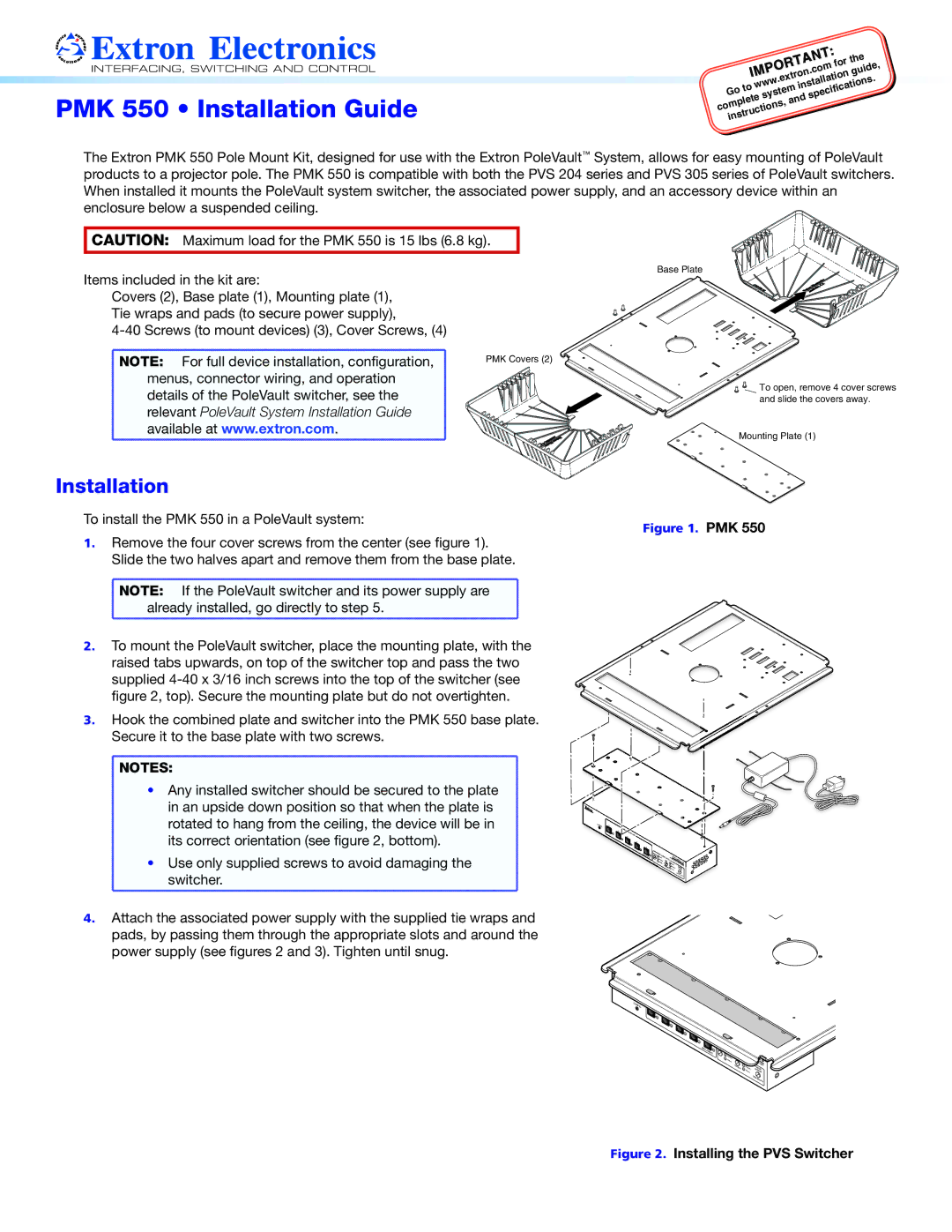
Base Plate
NOTE: | For full device installation, configuration, |
menus, connector wiring, and operation | |
details of the PoleVault switcher, see the | |
relevant PoleVault System Installation Guide | |
available at www.extron.com. | |
Installation
To install the PMK 550 in a PoleVault system:
PMK Covers (2)
To open, remove 4 cover screws and slide the covers away.
Mounting Plate (1)
Figure 1. PMK 550
1. | Remove the four cover screws from the center (see figure 1). | |
| Slide the two halves apart and remove them from the base plate. | |
| NOTE: | If the PoleVault switcher and its power supply are |
| already installed, go directly to step 5. | |
2. | To mount the PoleVault switcher, place the mounting plate, with the | |
| raised tabs upwards, on top of the switcher top and pass the two | |
| supplied | |
| figure 2, top). Secure the mounting plate but do not overtighten. | |
3. | Hook the combined plate and switcher into the PMK 550 base plate. | |
| Secure it to the base plate with two screws. | |
![]() NOTES:
NOTES:
• Any installed switcher should be secured to the plate in an upside down position so that when the plate is rotated to hang from the ceiling, the device will be in its correct orientation (see figure 2, bottom).
• Use only supplied screws to avoid damaging the switcher.
4.Attach the associated power supply with the supplied tie wraps and pads, by passing them through the appropriate slots and around the power supply (see figures 2 and 3). Tighten until snug.
| 5 |
AUX | AUDIIO |
| |
| SENSOR |
| SENSITIVITY |
CONFIG | 1 |
2 | S |
| 3 |
4
5
XA | T |
|
|
|
|
|
|
|
INPU | A |
|
|
|
|
|
| |
AU |
|
|
|
|
|
| ||
UDIO |
| PEAK UDIO | LEV | EL | POLE | ULT305SA | R | |
|
| NORMAL |
| |||||
|
| MIC |
| IP | ||||
|
| SIGNA | T | ADJUST |
| |||
|
|
| VOICELIF |
| PEAK |
| SWITCHE | |
|
|
|
| NORMAL | PA |
| ||
|
|
|
|
| GING |
| ||
|
|
|
|
| SIGNAL |
| SENSOR |
|
|
|
|
|
|
|
| SENSITIVITY | |