Installation and Operation, cont’d
OIDUA
PMOC |
RETU |
|
|
| M |
|
| GR | INO |
|
| RTO | |
| 1B |
| |
| 29 |
| H |
| 1 |
| IHS- |
3 2 | NO | EVEL | TF |
6 5 4 | L GORSRES |
| |
OI.DNUOAM.MPOSNDD
Figure 2-2 — Through-desk mounting
4. | Cut out the material from the installation area with a |
| jigsaw. Check the opening size by inserting the interface |
| part way through the hole. If needed, use a saw, file or |
| sandpaper to enlarge the hole. Smooth the edges of the |
| hole with sandpaper. |
5. | Drill pilot holes 1/4” (6.4 mm) deep, and 3/32” (2 mm) |
| diameter in the underside or inside (concealed side) of the |
| furniture where the interface will be located. |
6. | Secure the interface to the desk with the provided wood |
| screws. |
7. | To adjust the height of the interface within the desk, slide |
| the interface up or down to the desired position, then |
| tighten the screws that attach the brackets to the interface. |
Rack mounting (RGB 198 only)
1. | Remove rubber feet if they were previously installed on |
| the bottom of the interface. |
2. | Mount the interface on either side of an 19" 1U Universal |
| Rack Shelf (part # |
| screws to secure it to the shelf. See figure |
3.Install blank panel(s) or other unit(s) on the rack shelf.
4.Attach the rack shelf to the rack using the supplied bolts.
6" Deep Rack Shelf | 1/4 Rack Width Front False |
| Faceplate |
Front false ![]() faceplate uses 2
faceplate uses 2 ![]() screws.
screws. ![]()
![]()
RGB | 198 |
Use 2 mounting holes.
(2)
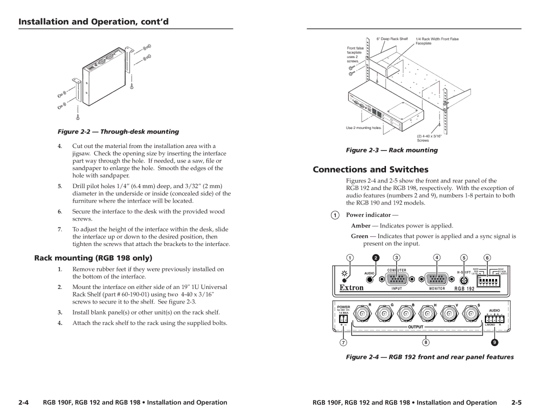
Figure 2-3 — Rack mounting
Connections and Switches
Figures 2-4 and 2-5 show the front and rear panel of the
RGB 192 and the RGB 198, respectively. With the exception of audio features (numbers 2 and 9), numbers 1-8 pertain to both the RGB 190 and 192 models.
1Power indicator —
Amber — Indicates power is applied.
Green — Indicates that power is applied and a sync signal is present on the input.
1 | 2 | 3 | 4 | 5 |
|
| 6 |
|
|
|
|
| C O M P U T E R |
| H - S H I F T | S E R R |
|
|
|
| D D S P |
| AUDIO |
| S O G |
|
|
|
| N O M O N . | ||
|
|
| L E V E L |
|
|
|
| M . AU D I O | ||
|
|
|
|
| ON |
|
|
|
|
|
|
|
|
|
| 1 | 2 | 3 | 4 | 5 | 6 |
|
| I N P U T | M O N I T O R | R G B 1 9 2 |
|
|
|
|
| |
POWER |
|
|
|
|
|
|
| AUDIO | ||
|
|
|
|
|
|
| ||||
1A MAX. |
|
|
|
|
|
|
|
|
|
|
L/MONO | R |
7 | 8 | 9 |
Figure 2-4 — RGB 192 front and rear panel features
RGB 190F, RGB 192 and RGB 198 • Installation and Operation | RGB 190F, RGB 192 and RGB 198 • Installation and Operation |