Instaltal lationandandOperation,cont’d
Installation Overview
This is an overview of the installation process. You will find detailed installation and operation instructions in this chapter.
Install and set up the RGB 190F, RGB 192 or RGB 198 interfaces by following these basic steps:
1Turn off all of the equipment (computers, remote controls, interface, projector/monitor, local monitor and speakers or other audio device). Disconnect the power cords from the power source.
2Install the rubber feet for tabletop use, or install the appropriate brackets to rack mount the interface. See Mounting the Interfaces below.
3Connect the input (computer video and audio (RGB 192 and 198 only)) and outputs (display, local monitor, and audio (RGB 192 and 198 only)). See Connections and Switches in this chapter.
4Set the front panel DIP switches. See Connections and Switches, in this chapter, as a guide.
5Connect power cords and turn on the devices: output devices (projector, monitors, speakers (RGB 192 and 198 only)), interface, and the source computer.
6Adjust horizontal centering and set the Level DIP switch to obtain the best picture.
Mounting the Interfaces
The interfaces provide several mounting options: tabletop placement,
Tabletop placement
For tabletop or desktop placement only, install the
Under-desk mounting
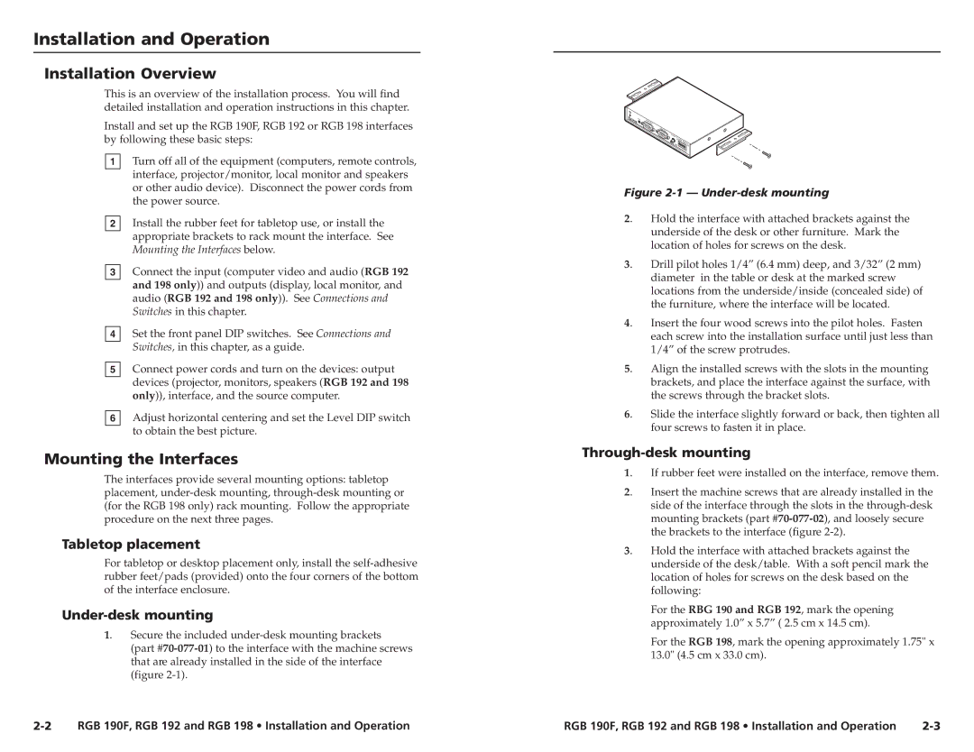
1. | Secure the included |
| (part |
| that are already installed in the side of the interface |
| (figure |
Figure 2-1 — Under-desk mounting
2. | Hold the interface with attached brackets against the |
| underside of the desk or other furniture. Mark the |
| location of holes for screws on the desk. |
3. | Drill pilot holes 1/4” (6.4 mm) deep, and 3/32” (2 mm) |
| diameter in the table or desk at the marked screw |
| locations from the underside/inside (concealed side) of |
| the furniture, where the interface will be located. |
4. | Insert the four wood screws into the pilot holes. Fasten |
| each screw into the installation surface until just less than |
| 1/4” of the screw protrudes. |
5. | Align the installed screws with the slots in the mounting |
| brackets, and place the interface against the surface, with |
| the screws through the bracket slots. |
6. | Slide the interface slightly forward or back, then tighten all |
| four screws to fasten it in place. |
Through-desk mounting
1. | If rubber feet were installed on the interface, remove them. |
2. | Insert the machine screws that are already installed in the |
| side of the interface through the slots in the |
| mounting brackets (part |
| the brackets to the interface (figure |
3. | Hold the interface with attached brackets against the |
| underside of the desk/table. With a soft pencil mark the |
| location of holes for screws on the desk based on the |
| following: |
For the RBG 190 and RGB 192, mark the opening approximately 1.0” x 5.7” ( 2.5 cm x 14.5 cm).
For the RGB 198, mark the opening approximately 1.75" x 13.0" (4.5 cm x 33.0 cm).
RGB 190F, RGB 192 and RGB 198 • Installation and Operation | RGB 190F, RGB 192 and RGB 198 • Installation and Operation |