RGB 408, RGB 404, RGB 402, RGB 400 Series, RGB 406 specifications
The Extron Electronic RGB 400 Series is a powerful line of RGBHV distribution amplifiers designed to meet the demands of professional audio-visual installations. This series encompasses several models, including the RGB 406, RGB 402, RGB 404, and RGB 408, each tailored to specific applications while maintaining the high-quality performance expected from Extron products.One of the standout features of the RGB 400 Series is its exceptional video quality. These distribution amplifiers support resolutions up to 1600x1200 and 1080p, ensuring that users can deliver crystal-clear images without degradation over extended distances. The units provide precise signal amplification and distribution, making them ideal for large venues such as auditoriums, conference rooms, and classrooms.
The RGB 406 model, for instance, is designed to handle up to six inputs and provides a robust output for distribution, making it suitable for installations that require multiple sources. The RGB 402, with its unique two input capacity, offers a more compact solution while still delivering outstanding performance. For those needing four inputs, the RGB 404 serves as an efficient choice, ensuring that users have seamless switching capabilities.
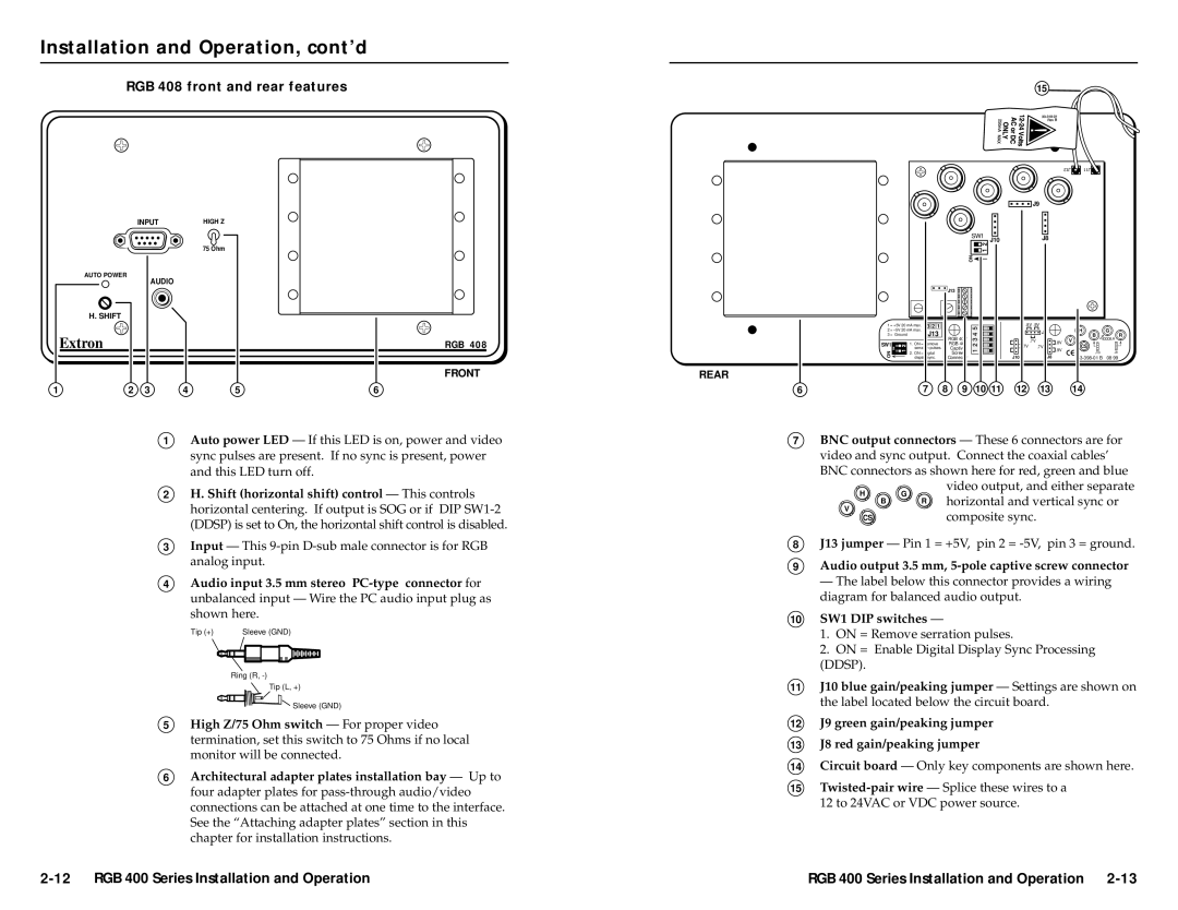
Meanwhile, the RGB 408 supports an extensive eight input capacity, catering to complex AV environments where multiple source devices are in use. The series also incorporates features such as automatic gain control and DC coupling, which enhance the overall signal integrity and minimize distortion.
Each model comes equipped with Extron's advanced technologies, including signal isolation and ground loop prevention, reducing the chances of interference and ensuring a reliable signal path. With user-friendly design considerations, the RGB 400 Series incorporates easy-to-use controls and LED indicators for simple operation and monitoring.
Additionally, the series supports a variety of connector types, providing installation versatility and compatibility with various equipment. The inclusion of robust metal enclosures ensures durability, while also allowing for rack mounting to maximize space efficiency in equipment rooms.
In conclusion, the Extron Electronic RGB 400 Series, featuring the RGB 406, RGB 402, RGB 404, and RGB 408 models, is an excellent choice for professionals seeking high-performance RGBHV distribution amplifiers. With their high-quality video output, versatile input options, advanced technologies, and reliability, these units cater to a broad range of AV installation needs, making them a staple in the professional AV industry.

