Installation and Operation, cont’d
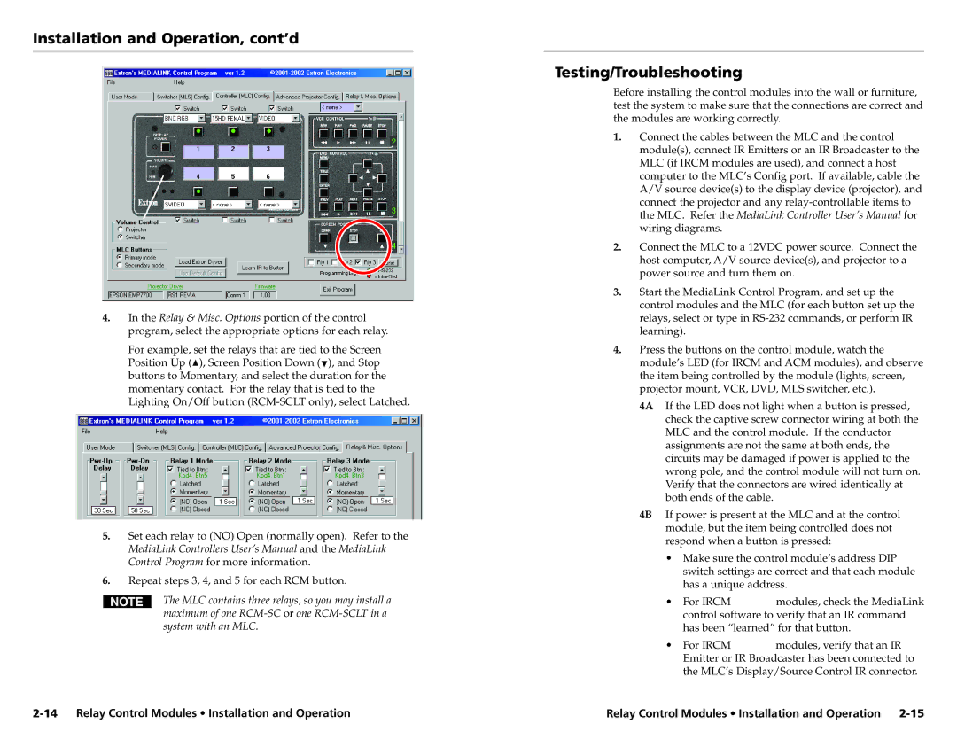
4.In the Relay & Misc. Options portion of the control program, select the appropriate options for each relay.
For example, set the relays that are tied to the Screen
Position Up (![]() ), Screen Position Down (
), Screen Position Down (![]() ), and Stop buttons to Momentary, and select the duration for the momentary contact. For the relay that is tied to the Lighting On/Off button
), and Stop buttons to Momentary, and select the duration for the momentary contact. For the relay that is tied to the Lighting On/Off button
5.Set each relay to (NO) Open (normally open). Refer to the MediaLink Controllers User’s Manual and the MediaLink Control Program for more information.
6.Repeat steps 3, 4, and 5 for each RCM button.
The MLC contains three relays, so you may install a maximum of one
Testing/Troubleshooting
Before installing the control modules into the wall or furniture, test the system to make sure that the connections are correct and the modules are working correctly.
1.Connect the cables between the MLC and the control module(s), connect IR Emitters or an IR Broadcaster to the MLC (if IRCM modules are used), and connect a host computer to the MLC’s Config port. If available, cable the A/V source device(s) to the display device (projector), and connect the projector and any
2.Connect the MLC to a 12VDC power source. Connect the host computer, A/V source device(s), and projector to a power source and turn them on.
3.Start the MediaLink Control Program, and set up the control modules and the MLC (for each button set up the relays, select or type in
4.Press the buttons on the control module, watch the module’s LED (for IRCM and ACM modules), and observe the item being controlled by the module (lights, screen, projector mount, VCR, DVD, MLS switcher, etc.).
4A If the LED does not light when a button is pressed, check the captive screw connector wiring at both the MLC and the control module. If the conductor assignments are not the same at both ends, the circuits may be damaged if power is applied to the wrong pole, and the control module will not turn on. Verify that the connectors are wired identically at both ends of the cable.
4B If power is present at the MLC and at the control module, but the item being controlled does not respond when a button is pressed:
•Make sure the control module’s address DIP switch settings are correct and that each module has a unique address.
• | For IRCM | modules, check the MediaLink |
| control software to verify that an IR command | |
| has been “learned” for that button. | |
• | For IRCM | modules, verify that an IR |
Emitter or IR Broadcaster has been connected to the MLC’s Display/Source Control IR connector.
Relay Control Modules • Installation and Operation |