Installation and Operation, cont’d
A B C D E | A B C D E |
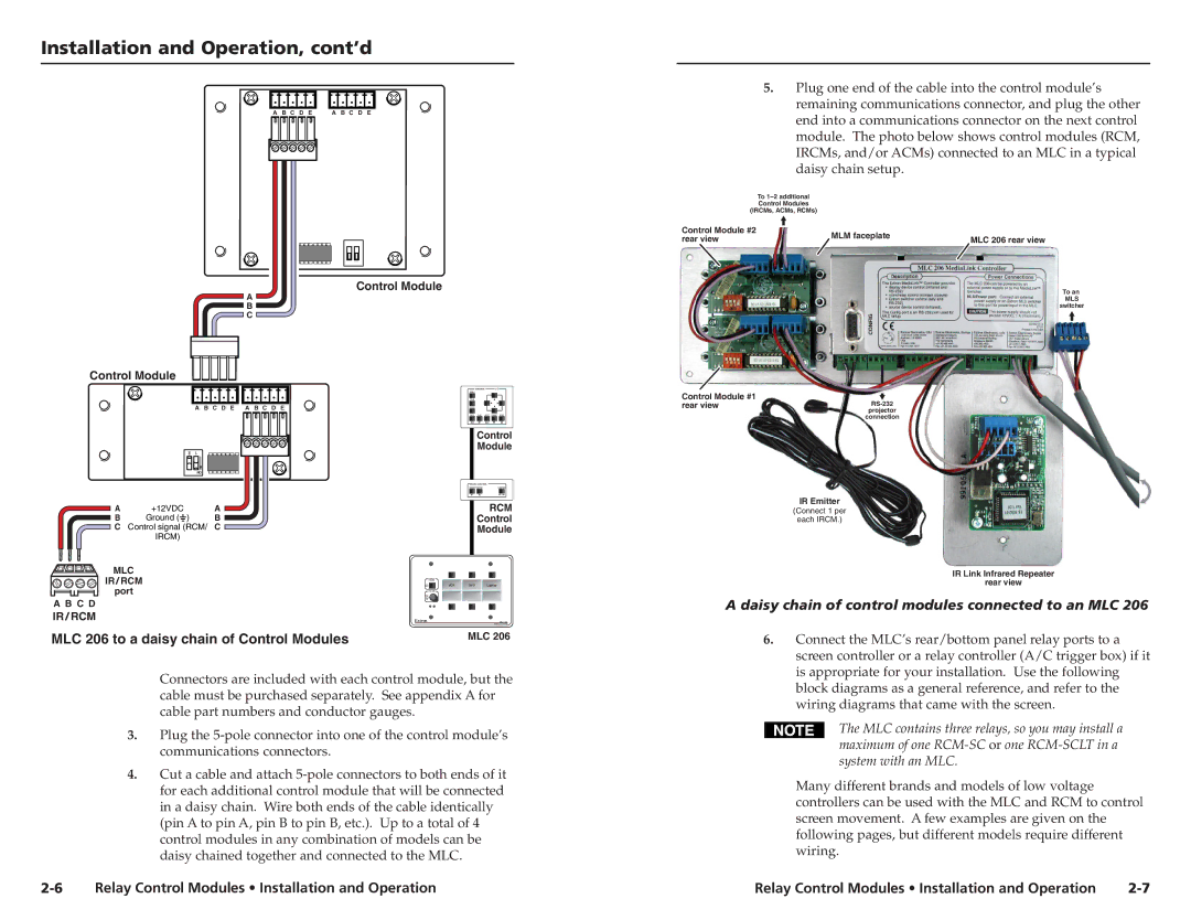
5.Plug one end of the cable into the control module’s remaining communications connector, and plug the other end into a communications connector on the next control module. The photo below shows control modules (RCM, IRCMs, and/or ACMs) connected to an MLC in a typical daisy chain setup.
To |
|
| |
Control Modules |
|
| |
(IRCMs, ACMs, RCMs) |
|
| |
Control Module #2 | MLM faceplate |
| |
rear view | MLC 206 rear view | ||
|
Control Module
A
B
C
Control Module
A B C D E | A B C D E |
|
|
| 2 | 1 |
|
| |
|
|
|
|
|
|
|
|
|
|
|
|
|
|
|
|
|
|
|
|
| ON |
|
|
A | +12VDC |
|
| A | |||
B | Ground ( |
| ) |
|
| B | |
|
|
| |||||
CControl signal (RCM/ C
IRCM)
DVD CONTROL | Tx |
MENU |
|
TITLE
ENTER
REW PLAY NEXT PAUSE STOP
Control Module
ROOM CONTROL
RCM
Control
Module
To an
MLS
switcher
Control Module #1
rear viewRS-232projector
connection
IR Emitter
(Connect 1 per
each IRCM.)
MLC |
|
|
|
IR / RCM | VCR | DVD | Laptop |
port |
|
|
|
A B C D |
|
|
|
IR / RCM | Extron | MLC 206 |
MLC 206 to a daisy chain of Control Modules |
| MLC 206 |
Connectors are included with each control module, but the cable must be purchased separately. See appendix A for cable part numbers and conductor gauges.
3.Plug the
4.Cut a cable and attach
IR Link Infrared Repeater
rear view
A daisy chain of control modules connected to an MLC 206
6.Connect the MLC’s rear/bottom panel relay ports to a screen controller or a relay controller (A/C trigger box) if it is appropriate for your installation. Use the following block diagrams as a general reference, and refer to the wiring diagrams that came with the screen.
The MLC contains three relays, so you may install a maximum of one
Many different brands and models of low voltage controllers can be used with the MLC and RCM to control screen movement. A few examples are given on the following pages, but different models require different wiring.
Relay Control Modules • Installation and Operation | Relay Control Modules • Installation and Operation |