
TLP 350MV specifications
The Extron TLP 350MV is a cutting-edge touchpanel designed to facilitate intuitive control over AV systems, making it an ideal choice for educational, corporate, and commercial applications. Known for its robust capabilities and user-friendly interface, the TLP 350MV provides a seamless way to manage audio and video resources effectively.One of the standout features of the TLP 350MV is its brilliant 3.5-inch color touchscreen display. The high-resolution display offers vibrant colors and sharp visuals, enabling users to easily navigate through various control options. The responsive capacitive touch technology ensures that interactions are smooth and accurate, resulting in a fluid user experience.
The TLP 350MV is equipped with an Ethernet port, which enables it to connect directly to a network. This connectivity feature allows for remote operation and integration with Extron’s Global Configurator software, making it possible to customize configurations and control various devices within the AV system. Users can create personalized interfaces tailored to specific applications or room layouts, ensuring optimal functionality.
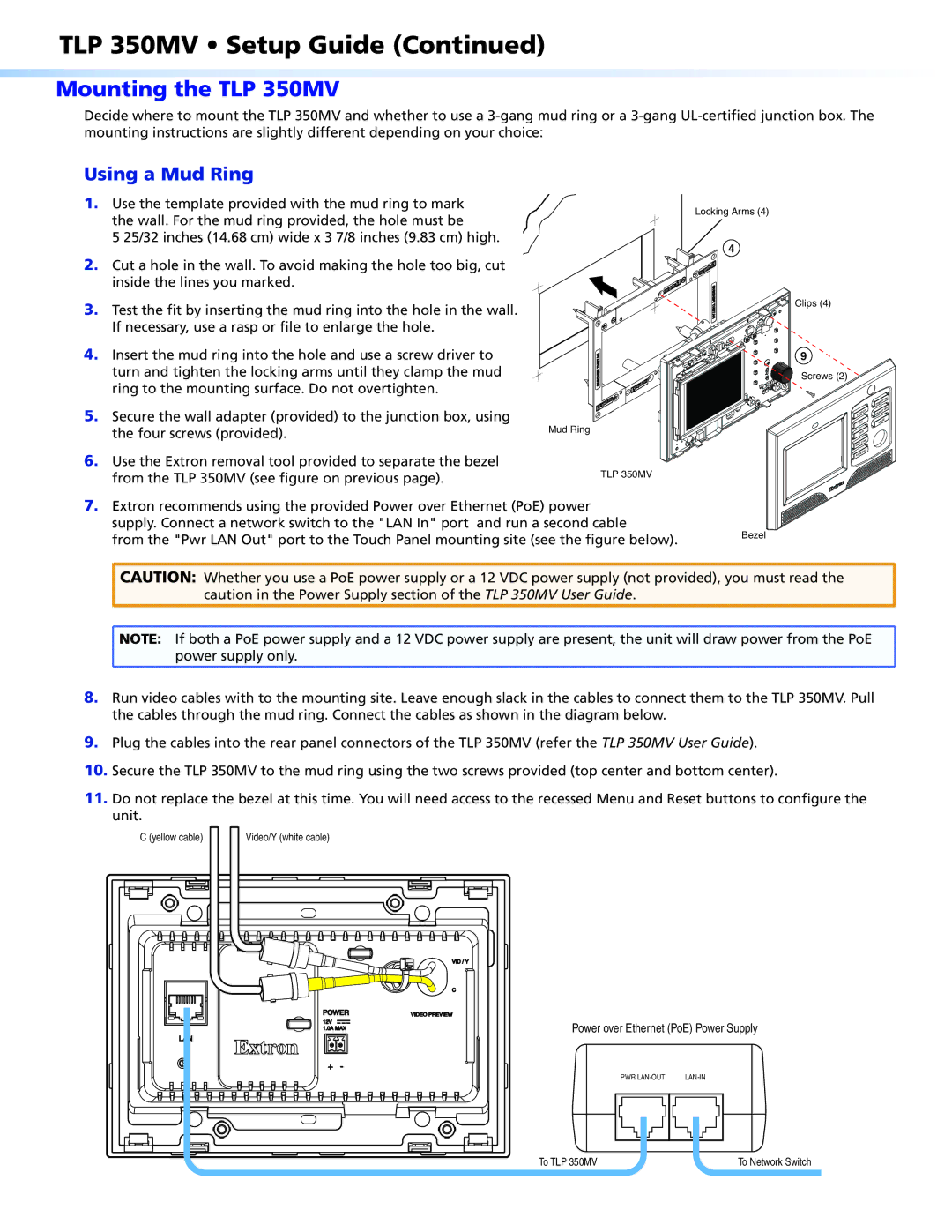
Another key characteristic of the TLP 350MV is its PoE (Power over Ethernet) capability. This technology allows the touchpanel to receive power through the same Ethernet cable used for data transmission, simplifying installation and reducing the need for additional power outlets. As a result, installers can enjoy a more straightforward deployment process while maintaining a clean and organized wiring system.
The TLP 350MV supports a variety of control protocols, making it compatible with numerous devices and systems. This versatility enables users to manage not only Extron devices but also third-party equipment, enhancing its usability in diverse environments. Furthermore, the touchpanel includes customizable buttons and icons, allowing users to easily control lighting, audio, video sources, and other functionalities with just a tap.
In terms of build quality, the TLP 350MV features a sleek and durable design, suitable for heavy usage in busy environments. Its compact size allows for convenient mounting on walls or tabletops, providing flexibility in deployment options.
In summary, the Extron TLP 350MV combines advanced features, intuitive design, and seamless integration capabilities, making it a powerful tool for simplifying AV control in various settings. Its user-friendly interface, PoE support, and broad compatibility position it as a comprehensive solution for anyone looking to enhance their AV experience.