XTP PI 400 Power Injector • Setup Guide (Continued)

Features

Indicators

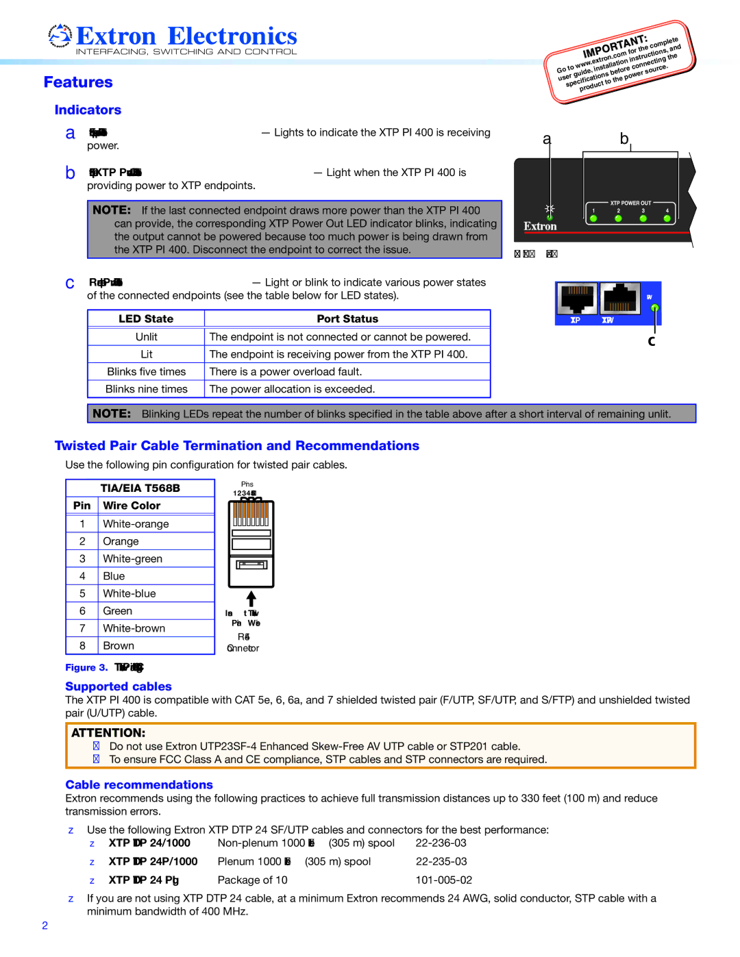
A Front panel power LED indicator — Lights to indicate the XTP PI 400 is receiving power.

B Front panel XTP Power Out LED indicators — Light when the XTP PI 400 is

providing power to XTP endpoints.

NOTE: If the last connected endpoint draws more power than the XTP PI 400 can provide, the corresponding XTP Power Out LED indicator blinks, indicating the output cannot be powered because too much power is being drawn from the XTP PI 400. Disconnect the endpoint to correct the issue.

C Rear panel Pwr LED indicators — Light or blink to indicate various power states of the connected endpoints (see the table below for LED states).

LED State

Port Status


Unlit

The endpoint is not connected or cannot be powered.


Lit

The endpoint is receiving power from the XTP PI 400.


Blinks five times

There is a power overload fault.


Blinks nine times

The power allocation is exceeded.


a b

XTP POWER OUT

1 2 3 4

Front Panel

PWR

XTP XTP PWR

c

NOTE: Blinking LEDs repeat the number of blinks specified in the table above after a short interval of remaining unlit.

Twisted Pair Cable Termination and Recommendations

Use the following pin configuration for twisted pair cables.


TIA/EIA T568B


Pins:


12345678


Pin

Wire Color


1

White-orange


2

Orange


3

White-green


4

Blue


5

White-blue


6

Green

Insert Twisted

7

White-brown


Pair Wires


RJ-45


8

Brown

Connector

Figure 3. Twisted Pair Cable Configuration

Supported cables

The XTP PI 400 is compatible with CAT 5e, 6, 6a, and 7 shielded twisted pair (F/UTP, SF/UTP, and S/FTP) and unshielded twisted pair (U/UTP) cable.

ATTENTION:

Do not use Extron UTP23SF-4 Enhanced Skew-Free AV UTP cable or STP201 cable.

To ensure FCC Class A and CE compliance, STP cables and STP connectors are required.

Cable recommendations

Extron recommends using the following practices to achieve full transmission distances up to 330 feet (100 m) and reduce transmission errors.

zz Use the following Extron XTP DTP 24 SF/UTP cables and connectors for the best performance:

zz

XTP DTP 24/1000

Non-plenum 1000 feet (305 m) spool

22-236-03

zz

XTP DTP 24P/1000

Plenum 1000 feet (305 m) spool

22-235-03

zz XTP DTP 24 Plug

Package of 10

101-005-02

zz If you are not using XTP DTP 24 cable, at a minimum Extron recommends 24 AWG, solid conductor, STP cable with a minimum bandwidth of 400 MHz.

2

Page 2
Image 2
Extron electronic XTP PI 400 Features, Indicators, Twisted Pair Cable Termination and Recommendations

XTP PI 400 specifications

Extron’s XTP PI 400 is a powerful and innovative product designed to meet the expanding needs of professional audio and video environments. As an integral component within the XTP Systems architecture, the XTP PI 400 provides a robust, reliable, and flexible solution for signal processing in various applications, from corporate settings to educational institutions and beyond.

One of the key features of the XTP PI 400 is its ability to distribute power over the same cabling infrastructure used for video signals. This eliminates the need for additional power supplies and simplifies installation, making it an ideal choice for spaces where cable management and accessibility are critical. The unit provides power to XTP transmitters, allowing for longer distances without compromising signal quality. It supports HDMI, DisplayPort, and other formats, ensuring compatibility across a wide range of multimedia devices.

Utilizing Extron’s innovative XTP technology, the XTP PI 400 supports real-time processing and low-latency signal transmission, making it suitable for live event scenarios and dynamic presentations. The XTP platform is built on twisted pair technology, allowing for transmission distances of up to 330 feet (100 meters) for high-definition video signals, while also featuring a built-in EDID management system. This capability ensures that connected devices communicate effectively and optimize signal quality.

The XTP PI 400 also boasts advanced features such as automatic switching and routing of signals, as well as seamless support for multiple resolutions and formats. This versatility makes it a valuable tool in any AV system, ensuring that users can easily manage their media content. Additionally, the product includes built-in diagnostic tools that provide real-time feedback and status reports, allowing users to troubleshoot issues quickly and effectively.

In terms of design, the XTP PI 400 is compact and rack-mountable, making it easy to integrate into existing AV racks or equipment enclosures. Its intuitive user interface and comprehensive setup options allow for customization and optimization based on specific installation needs. The unit is also engineered with high-quality components to ensure durability and reliable performance over time.

Overall, the Extron XTP PI 400 is a cutting-edge signal processing solution that combines advanced technology, user-friendly design, and exceptional performance. It stands out in the market as a versatile and dependable option for professional AV applications, making it an essential asset for any AV system installation.