XTP T USW 103 • Setup Guide (Continued)

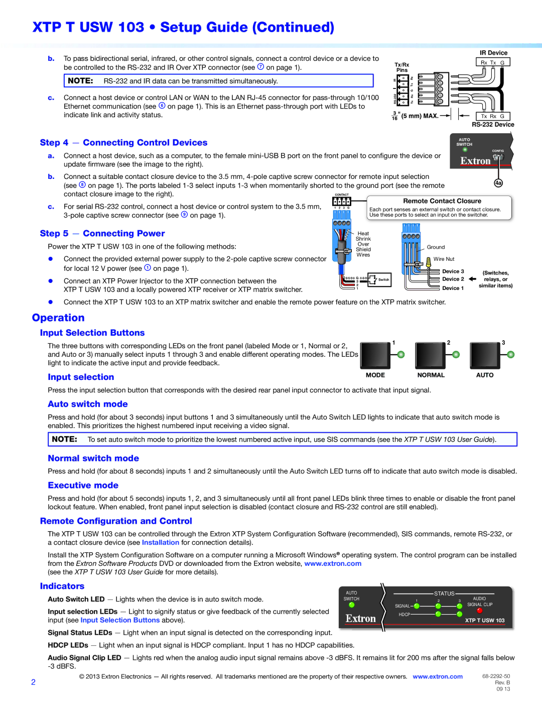
b.To pass bidirectional serial, infrared, or other control signals, connect a control device or a device to be controlled to the RS-232 and IR Over XTP connector (see G on page 1).

NOTE: RS-232 and IR data can be transmitted simultaneously.

c.Connect a host device or control LAN or WAN to the LAN RJ-45 connector for pass-through 10/100 Ethernet communication (see F on page 1). This is an Ethernet pass-through port with LEDs to indicate link and activity status.

IR Device

Tx/Rx

Rx Tx

G

Pins


IR

Rx


Tx


G

232

Rx

RS-

Tx

Tx Rx G

RS-232 Device

Step 4 Connecting Control Devices


SWITCH


AUTO


a.

Connect a host device, such as a computer, to the female mini-USB B port on the front panel to configure the device or

CONFIG


update firmware (see the image to the right).


b.

Connect a suitable contact closure device to the 3.5 mm, 4-pole captive screw connector for remote input selection


Ü


(see H on page 1). The ports labeled 1-3 select inputs 1-3 when momentarily shorted to the ground port (see the remote


contact closure image to the right).

CONTACT

Remote Contact Closure


c. For serial RS-232 control, connect a host device or control system to the 3.5 mm,


1 2 3 G

Each port senses an external switch or contact closure.


3-pole captive screw connector (see I on page 1).


Use these ports to select an input on the switcher.


Step 5 Connecting Power

Power the XTP T USW 103 in one of the following methods:

zz Connect the provided external power supply to the 2-pole captive screw connector for local 12 V power (see A on page 1).

zz Connect an XTP Power Injector to the XTP connection between the

XTP T USW 103 and a locally powered XTP receiver or XTP matrix switcher.

Heat


Shrink


Over


Ground


Shield


Wires


Wire Nut


Device 3

(Switches,


Switch


G


Device 2

relays, or

3


similar items)

2


Device 1

1


zz Connect the XTP T USW 103 to an XTP matrix switcher and enable the remote power feature on the XTP matrix switcher.

Operation

Input Selection Buttons

The three buttons with corresponding LEDs on the front panel (labeled Mode or 1, Normal or 2, and Auto or 3) manually select inputs 1 through 3 and enable different operating modes. The LEDs light to indicate the active input and provide feedback.

1

2

3

Input selection

MODE NORMAL AUTO

Press the input selection button that corresponds with the desired rear panel input connector to activate that input signal.

Auto switch mode

Press and hold (for about 3 seconds) input buttons 1 and 3 simultaneously until the Auto Switch LED lights to indicate that auto switch mode is enabled. This prioritizes the highest numbered input receiving a video signal.

NOTE: To set auto switch mode to prioritize the lowest numbered active input, use SIS commands (see the XTP T USW 103 User Guide).

Normal switch mode

Press and hold (for about 8 seconds) inputs 1 and 2 simultaneously until the Auto Switch LED turns off to indicate that auto switch mode is disabled.

Executive mode

Press and hold (for about 5 seconds) inputs 1, 2, and 3 simultaneously until all front panel LEDs blink three times to enable or disable the front panel lockout feature. When enabled, front panel input selection is disabled (contact closure and RS-232 control are still enabled).

Remote Configuration and Control

The XTP T USW 103 can be controlled through the Extron XTP System Configuration Software (recommended), SIS commands, remote RS-232, or a contact closure device (see Installation for connection details).

Install the XTP System Configuration Software on a computer running a Microsoft Windows® operating system. The control program can be installed from the Extron Software Products DVD or downloaded from the Extron website, www.extron.com

(see the XTP T USW 103 User Guide for more details).

Indicators

Auto Switch LED — Lights when the device is in auto switch mode.

AUTO


STATUS


AUDIO

SWITCH

1

2

3


SIGNAL


SIGNAL CLIP

Input selection LEDs — Light to signify status or give feedback of the currently selected


HDCP


input (see Input Selection Buttons above).


XTP T USW 103

Signal Status LEDs — Light when an input signal is detected on the corresponding input. HDCP LEDs — Light when an input signal is HDCP compliant. Input 1 has no HDCP capabilities.

Audio Signal Clip LED — Lights red when the analog audio input signal remains above -3 dBFS. It remains lit for 200 ms after the signal falls below -3 dBFS.

2

© 2013 Extron Electronics — All rights reserved. All trademarks mentioned are the property of their respective owners. www.extron.com

68-2292-50


Rev. B


09 13

Page 2
Image 2
Extron electronic XTP T USW 103 Connecting Control Devices, Connecting Power, Input Selection Buttons, Input selection

XTP T USW 103 specifications

The Extron XTP T USW 103 is a state-of-the-art technology designed to streamline audio and video signal distribution over a single twisted pair cable. Part of Extron's acclaimed XTP System, this device is ideal for various applications, such as classrooms, conference rooms, and other professional AV setups.

One of the standout features of the XTP T USW 103 is its ability to handle multiple high-definition video signals alongside audio and control signals. Supporting resolutions up to 4K, this device ensures sharp, clear images for any presentation or media playback. Additionally, it incorporates advanced signal processing technologies, such as HDMI, that allow for high bandwidth, ensuring that audio and video are transmitted without compromise.

The device uses Extron's proprietary XTP technology, which allows for the transmission of multi-format audio and video signals over long distances using CATx cable. This means that installations can be more flexible and cost-effective, as it reduces the need for multiple types of cables in a single setup.

Another defining characteristic of the XTP T USW 103 is its user-friendly interface. Featuring an intuitive design, it allows users to navigate and control the system with ease. The integrated scaling technology enables users to switch between different resolutions seamlessly, ensuring compatibility with a wide range of display devices.

In terms of management and configuration, the XTP T USW 103 supports Extron's Global Configurator software, which simplifies setup and control for AV professionals. This software allows for comprehensive system management, enabling remote monitoring and troubleshooting, thereby minimizing downtime during operation.

The XTP T USW 103 is also built with reliability in mind, featuring robust construction and thorough testing to meet the rigorous demands of professional environments.

In summary, the Extron XTP T USW 103 excels in delivering high-quality audio and video performance with its advanced transmission technologies and user-friendly features. This makes it a top choice for AV professionals looking to enhance their installation capabilities and provide exceptional solutions for their clients’ needs.