YCS SW6 MX specifications
Extron Electronics, a prominent name in the field of AV technology, has introduced the YCS SW6 MX, a high-performance switcher that caters to the increasing demands of modern audio-visual environments. The YCS SW6 MX is recognized for its outstanding versatility and reliability, making it a preferred choice for both educational and corporate settings.One of the standout features of the YCS SW6 MX is its ability to support various video resolutions, including 4K, ensuring that it can handle today's demanding video content. This capability is essential for environments where high-quality visuals are critical, such as classrooms with interactive displays or boardrooms equipped with high-resolution projectors. The switcher also incorporates advanced scaling technology that allows for seamless conversion between different resolutions, ensuring a smooth user experience.
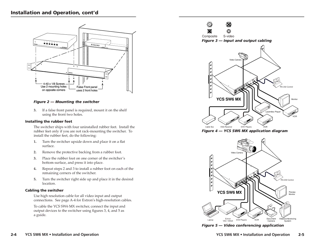
The YCS SW6 MX comes with six inputs and two outputs, allowing for flexible configuration options. This configuration makes it easy to connect multiple sources, such as laptops, document cameras, and other media devices, facilitating effortless switching during presentations or lectures. The built-in audio functionality supports various audio formats, providing an integrated solution that enhances the overall AV experience.
Furthermore, Extron has incorporated cutting-edge technologies in the YCS SW6 MX to ensure reliable operations. The switcher features HDMI 2.0 and HDCP 2.2 compliance, guaranteeing compatibility with the latest devices and content protection standards. Additionally, the inclusion of Extron's proprietary technologies aims to enhance signal integrity and reduce latency, further optimizing performance.
The user interface of the YCS SW6 MX has been designed with usability in mind. It offers a straightforward control mechanism, allowing operators to switch inputs or configure settings with ease. The device can be controlled via Extron’s extensive range of control solutions, including touch panels or third-party control systems, providing flexibility in management.
Robust built-quality is another characteristic of the YCS SW6 MX. Designed for durability and longevity, this switcher is an ideal investment for institutions seeking reliable performance over time. With its combination of cutting-edge technology, comprehensive features, and high-quality construction, the Extron YCS SW6 MX stands out as a powerful tool that meets the evolving demands of audio-visual applications.

