
BSS84 specifications
The Fairchild BSS84 is an N-channel MOSFET (Metal-Oxide-Semiconductor Field-Effect Transistor) widely recognized for its robust performance in various applications such as switching and amplification. Designed for low voltage and low current applications, it is particularly well-suited for portable devices and power management systems.One of the main features of the BSS84 is its low on-resistance, which minimizes power loss during operation. This characteristic is crucial for applications requiring high efficiency, as it contributes to reduced heat generation, thereby enhancing device longevity. With an RDS(on) value typically around 1.0 ohm, the BSS84 can efficiently handle moderate current loads, making it ideal for battery management systems and power multiplexing.
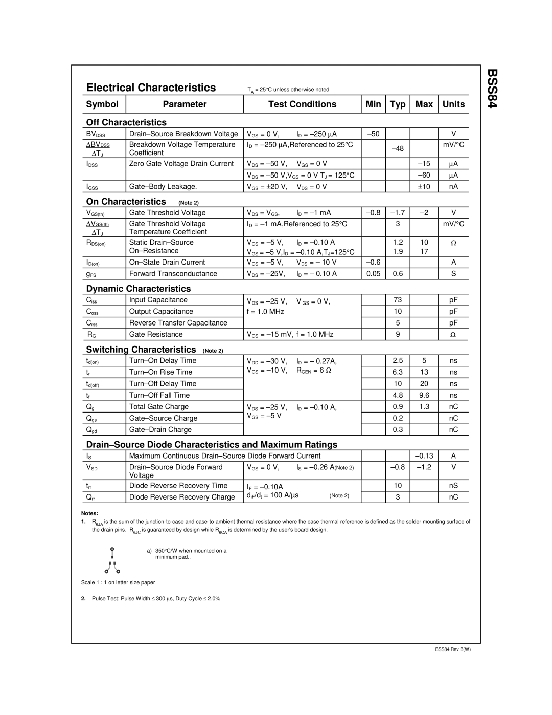
Another significant feature of the BSS84 is its low gate threshold voltage (VGS(th)), typically ranging from 0.8V to 3V. This allows the MOSFET to be easily driven by low-voltage logic levels, ensuring compatibility with modern microcontrollers and other digital circuitry. This attribute is particularly advantageous in handheld electronic devices where power efficiency and space-saving are paramount.
The BSS84 also showcases fast switching capabilities, contributing to its effectiveness in high-speed application environments. Its rise and fall times allow for rapid switching, which is essential in applications such as pulse width modulation (PWM) for motor control and switching power supplies. The capability to operate at high frequencies also aids in improving the efficiency of these systems.
In terms of packaging, the BSS84 is available in a variety of formats, including surface-mount options that enable designers to save space on printed circuit boards. This versatility in form factor makes it easily adaptable to a broad range of technologies from consumer electronics to industrial applications.
The BSS84 is built using advanced semiconductor technology, ensuring durability and reliability under varying environmental conditions. Its thermal characteristics allow for effective heat dissipation, enabling the MOSFET to maintain stable performance across a wide temperature range.
These features collectively make the Fairchild BSS84 a favored choice among engineers and designers in various sectors, particularly where efficiency, compactness, and reliability are critical. Whether in automotive, computing, or telecommunications, the BSS84 continues to serve as a crucial component in modern electronic designs.