FIRE CONTROL INSTRUMENTS, Inc.
MOUNTING
•On a
•On a
INSTALLATION
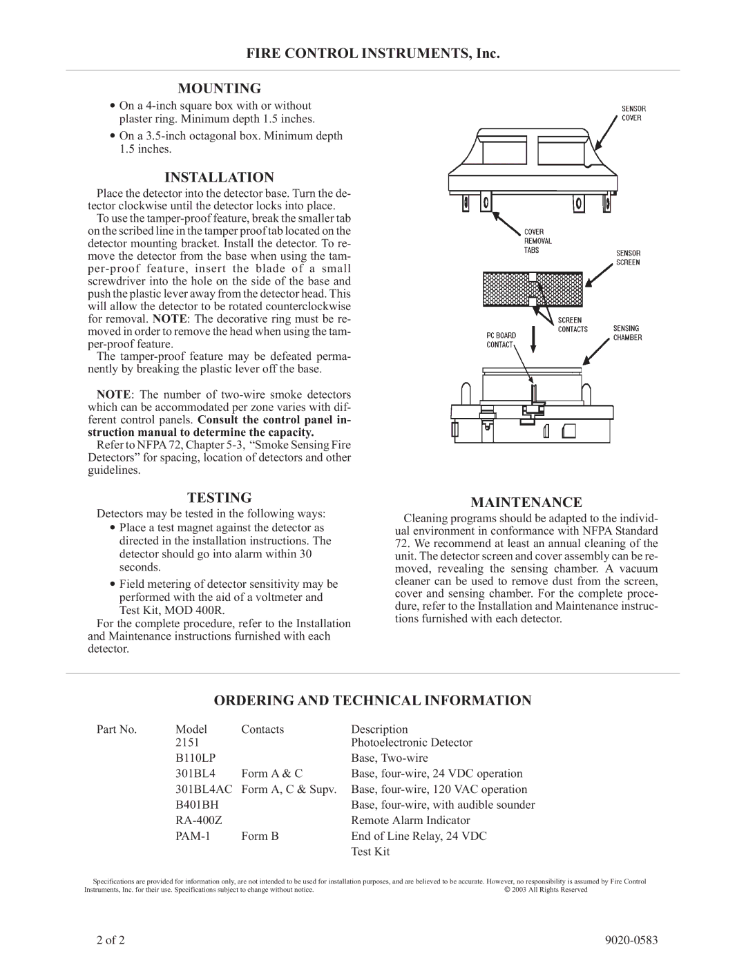
Place the detector into the detector base. Turn the de- tector clockwise until the detector locks into place.
To use the
The
NOTE: The number of
Refer to NFPA 72, Chapter
TESTING
Detectors may be tested in the following ways:
•Place a test magnet against the detector as directed in the installation instructions. The detector should go into alarm within 30 seconds.
•Field metering of detector sensitivity may be performed with the aid of a voltmeter and Test Kit, MOD 400R.
For the complete procedure, refer to the Installation and Maintenance instructions furnished with each detector.
MAINTENANCE
Cleaning programs should be adapted to the individ- ual environment in conformance with NFPA Standard
72.We recommend at least an annual cleaning of the unit. The detector screen and cover assembly can be re- moved, revealing the sensing chamber. A vacuum cleaner can be used to remove dust from the screen, cover and sensing chamber. For the complete proce- dure, refer to the Installation and Maintenance instruc- tions furnished with each detector.
ORDERING AND TECHNICAL INFORMATION
Part No. | Model | Contacts | Description |
| 2151 |
| Photoelectronic Detector |
| B110LP |
| Base, |
| 301BL4 | Form A & C | Base, |
| 301BL4AC | Form A, C & Supv. | Base, |
| B401BH |
| Base, |
|
| Remote Alarm Indicator | |
| Form B | End of Line Relay, 24 VDC | |
|
|
| Test Kit |
Specifications are provided for information only, are not intended to be used for installation purposes, and are believed to be accurate. However, no responsibility is assumed by Fire Control
Instruments, Inc. for their use. Specifications subject to change without notice. | © 2003 All Rights Reserved |
2 of 2 |