INSTALLATION, OPERATION AND TROUBLESHOOTING GUIDE | FLUID COMPONENTS INTL |
Wiring the Instrument into the Customer’s Application:
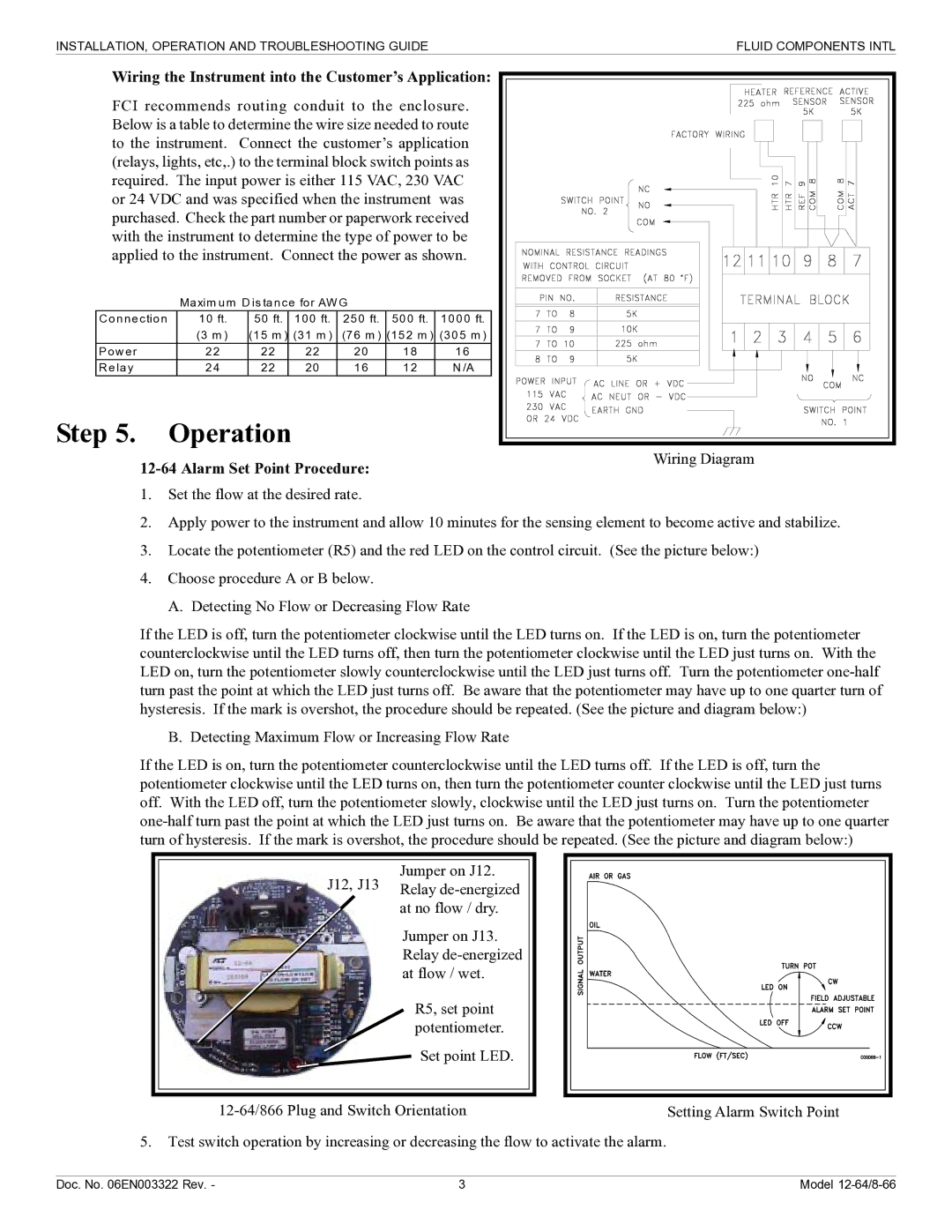
FCI recommends routing conduit to the enclosure. Below is a table to determine the wire size needed to route to the instrument. Connect the customer’s application (relays, lights, etc,.) to the terminal block switch points as required. The input power is either 115 VAC, 230 VAC or 24 VDC and was specified when the instrument was purchased. Check the part number or paperwork received with the instrument to determine the type of power to be applied to the instrument. Connect the power as shown.
| Maxim um D is tance for AWG |
|
| |||
C onnection | 10 ft. | 50 ft. | 100 ft. | 250 ft. | 500 ft. | 1000 ft. |
| (3 m ) | (15 m ) | (31 m ) | (76 m ) | (152 m ) | (305 m ) |
Pow er | 22 | 22 | 22 | 20 | 18 | 16 |
R elay | 24 | 22 | 20 | 16 | 12 | N /A |
Step 5. Operation
| Wiring Diagram |
|
1.Set the flow at the desired rate.
2.Apply power to the instrument and allow 10 minutes for the sensing element to become active and stabilize.
3.Locate the potentiometer (R5) and the red LED on the control circuit. (See the picture below:)
4.Choose procedure A or B below.
A. Detecting No Flow or Decreasing Flow Rate
If the LED is off, turn the potentiometer clockwise until the LED turns on. If the LED is on, turn the potentiometer counterclockwise until the LED turns off, then turn the potentiometer clockwise until the LED just turns on. With the LED on, turn the potentiometer slowly counterclockwise until the LED just turns off. Turn the potentiometer
B. Detecting Maximum Flow or Increasing Flow Rate
If the LED is on, turn the potentiometer counterclockwise until the LED turns off. If the LED is off, turn the potentiometer clockwise until the LED turns on, then turn the potentiometer counter clockwise until the LED just turns off. With the LED off, turn the potentiometer slowly, clockwise until the LED just turns on. Turn the potentiometer
Jumper on J12.
J12, J13 Relay
Jumper on J13. Relay
R5, set point potentiometer.
Set point LED.
Setting Alarm Switch Point |
5.Test switch operation by increasing or decreasing the flow to activate the alarm.
Doc. No. 06EN003322 Rev. - | 3 | Model |