Manuals
/
Fender
/
Home Audio
/
Stereo Amplifier
Fender
Twin Amplifier
owner manual
Twin Front Panel Functions, Twin Rear Panel Functions Fig
Models:
Twin Amplifier
1
3
8
8
Download
8 pages
48.03 Kb
1
2
3
4
5
6
7
8
Specification
Twin Block Diagram
Twin Amp Sound Settings
Low Power Option
Page 3
Image 3
Page 2
Page 4
Page 3
Image 3
Page 2
Page 4
Contents
TYPE PR266
TwinOwner,sAmpManual
Introduction
Twin Amp Sound Settings
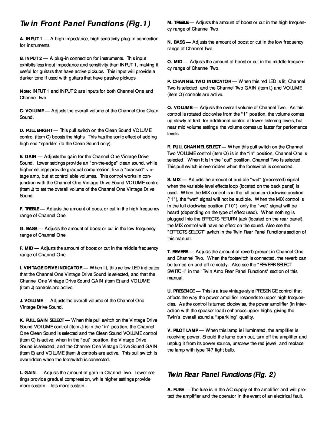
Twin Rear Panel Functions Fig
Twin Front Panel Functions Fig.1
Fig. Fig
Output Tube Bias Adjustment Instructions
LOW POWER OPTION
1 2 Gain
Twin Block Diagram
Specifications
Top
Page
Image
Contents