Features & Controls |
| |
of the Zero Turn Rider |
| |
Please take a moment and familiarize |
|
|
yourself with the name, location, and |
|
|
function of these controls so that you | A |
|
will better understand the safety and |
| |
|
| |
operating instructions provided in this |
| A |
manual. |
| |
| B | |
| C | |
|
| |
H | E |
|
|
| |
J
D
K
I
F
G
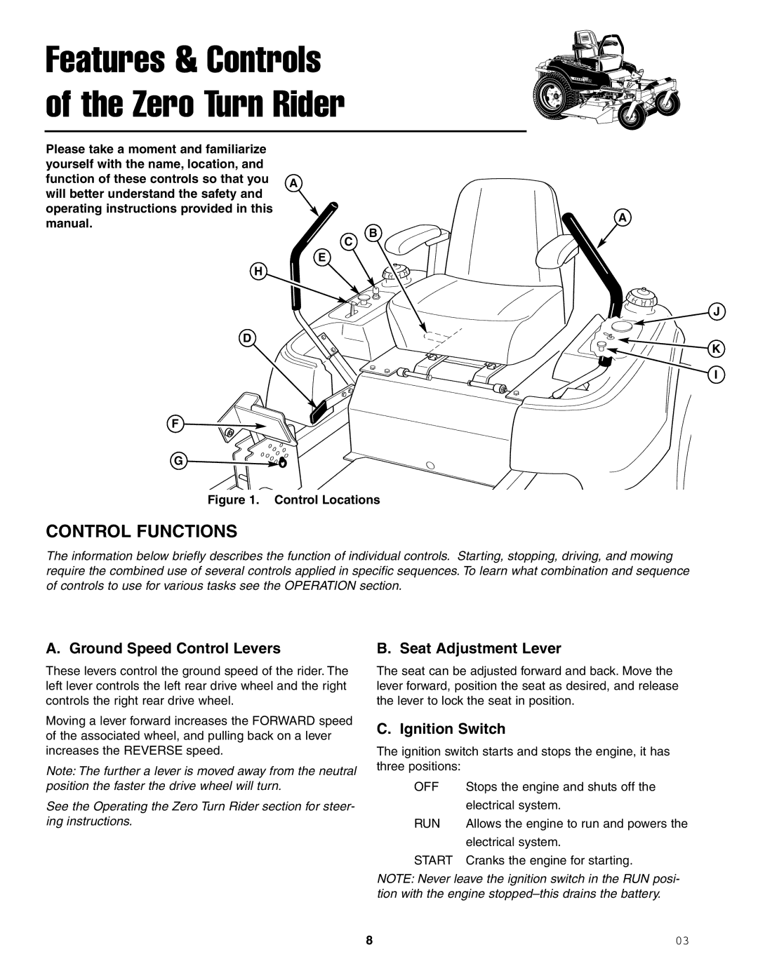
Figure 1. Control Locations
CONTROL FUNCTIONS
The information below briefly describes the function of individual controls. Starting, stopping, driving, and mowing require the combined use of several controls applied in specific sequences. To learn what combination and sequence of controls to use for various tasks see the OPERATION section.
A. Ground Speed Control Levers
These levers control the ground speed of the rider. The left lever controls the left rear drive wheel and the right controls the right rear drive wheel.
Moving a lever forward increases the FORWARD speed of the associated wheel, and pulling back on a lever increases the REVERSE speed.
Note: The further a lever is moved away from the neutral position the faster the drive wheel will turn.
See the Operating the Zero Turn Rider section for steer- ing instructions.
B. Seat Adjustment Lever
The seat can be adjusted forward and back. Move the lever forward, position the seat as desired, and release the lever to lock the seat in position.
C. Ignition Switch
The ignition switch starts and stops the engine, it has three positions:
OFF | Stops the engine and shuts off the |
| electrical system. |
RUN | Allows the engine to run and powers the |
| electrical system. |
START | Cranks the engine for starting. |
NOTE: Never leave the ignition switch in the RUN posi- tion with the engine
8 | 03 |