BGF48KAV15, BGF36KAV15 specifications
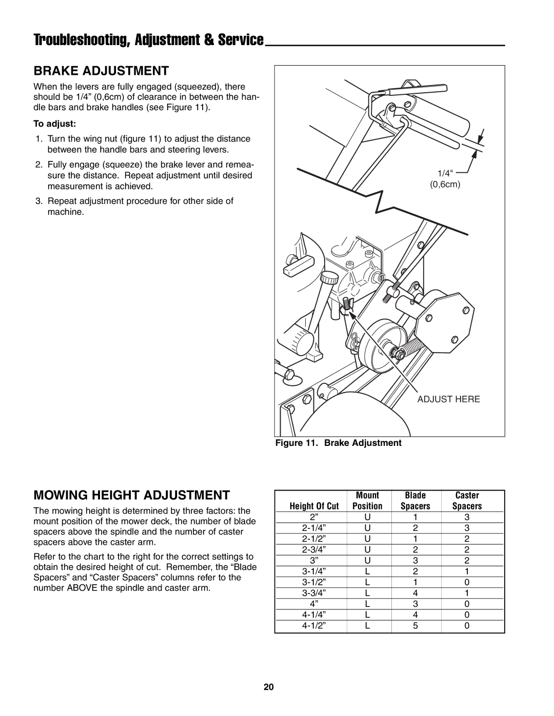
Ferris Industries has established itself as a prominent name in the lawn care and landscaping industry, known for its durable and efficient commercial mowers. Among its product range, the Ferris BGF36KAV15 and BGF48KAV15 models stand out for their superior performance and innovative features.The Ferris BGF36KAV15 is a compact, stand-on mower designed for maximum maneuverability and efficiency in tight spaces. With a 36-inch cutting deck, it is ideal for residential lawns, commercial properties, and landscape maintenance. Powered by a robust Kohler engine, this model delivers reliable performance and can handle various terrain types with ease. The BGF36KAV15 features Ferris's patented SuperB SRT (Suspension Ride Technology), which ensures a smoother ride and reduces operator fatigue during long periods of use. The cutting height is easily adjustable, providing versatility in different grass types and conditions.
On the other hand, the BGF48KAV15 offers a larger 48-inch cutting deck, making it suitable for larger properties and more extensive commercial applications. This model is also powered by a professional-grade Kohler engine, ensuring high productivity and efficiency. Similar to the BGF36KAV15, this mower is equipped with the SuperB SRT system, enhancing ride comfort and stability on uneven ground. The BGF48KAV15 also boasts an innovative cutting system that delivers a clean and precise cut, improving the overall appearance of the lawn.
Both models come with several advanced technologies that enhance user experience and safety. The operator platform is designed for ergonomic comfort, reducing strain during operation. The mowers feature a durable chassis and high-quality components that ensure longevity and reliability. Additionally, the intuitive control layout allows for easy operation, making these mowers accessible to users of all experience levels.
In summary, the Ferris BGF36KAV15 and BGF48KAV15 are exceptional stand-on mowers that combine power, maneuverability, and advanced technology. Their features, including adjustable cutting heights, robust engines, and superior ride comfort, make them ideal choices for both commercial and residential lawn care. With Ferris Industries' commitment to quality and innovation, these mowers are poised to deliver outstanding performance and results in the field.

