S-2A specifications
Fireboy- Xintex, LTD S-2A is a state-of-the-art marine fire suppression system that is specifically designed to protect valuable assets and ensure safety on board vessels. This advanced system utilizes innovative technologies and features to deliver reliable and effective fire protection, making it an essential addition to any marine environment.One of the standout features of the S-2A system is its ability to automatically detect and suppress fires in enclosed spaces, such as engine compartments, galleys, and other areas prone to fire hazards. This is achieved through the use of advanced thermal detectors that monitor temperature changes and activate the suppression mechanism when necessary, ensuring a swift response to any fire outbreak.
The S-2A system employs a clean agent fire suppression technology, utilizing an environmentally friendly and non-toxic gas, which is safe for both people and the marine environment. This clean agent is designed to quickly extinguish fires without causing damage to equipment or leaving a residue, making it ideal for sensitive areas on the vessel.
Another critical characteristic of the Fireboy S-2A system is its compact design, which allows for easy installation in various types of vessels, including yachts, commercial ships, and recreational boats. The system is engineered to fit into tight spaces while providing optimal fire protection.
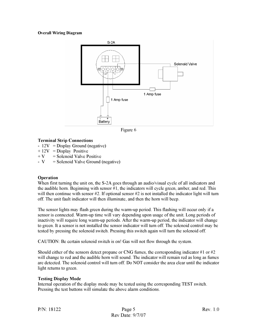
The S-2A also features a user-friendly interface that allows for easy monitoring and control. With an integrated alarm system, users are promptly alerted to any issues, enhancing overall safety and promoting quick action and response.
Additional benefits of the Fireboy- Xintex, LTD S-2A include its durability and longevity. The system is constructed with high-quality materials designed to withstand harsh marine conditions, ensuring consistent performance over time.
Overall, the Fireboy- Xintex, LTD S-2A fire suppression system represents a significant advancement in marine safety technology. Its combination of automatic detection, clean agent suppression, compact design, and durable construction makes it a smart choice for anyone looking to enhance the safety of their vessel. Investing in such a system can provide peace of mind and protect both people and property from the devastating impacts of marine fires.

