one existing frame hole must be drilled out to bolt the upper bracket tp the frame due to a heat shield covering the hole from the inside of the vehicle frame. This heat shield material must be removed using a 7/16" drill bit to allow the fastener to pass through the hole.
STEP 6 - INSTALL THE AIR LINE AND THE INFLATION VALVE
Uncoil the air line tubing and cut it into two equal lengths. DO NOT FOLD OR KINK THE TUBING. Try to make the cut as square as possible. Insert one end of the tubing into the elbow fitting installed in the top of the air helper spring. Push the tubing into the fitting as far as possible refer to Figure "A".
Select a location on the vehicle for the air inflation valves. The location can be on the bumper or the body of the vehicle, as long as it is in a protected location so the valve will not be damaged, but maintain accessibility for the air chuck see Figure "C". Drill a 5/16" hole and install the air inflation valve using two 5/16" flat washers per valve as supports see Figure "D". Run the tubing from the air helper spring to the inflation valve, routing it to avoid direct heat from the engine, exhaust pipe, and away from sharp edges. Thermal sleeves have been provided for these conditions. If a thermal sleeve is required simply slide the sleeve over the air line tubing to the location requiring protection. The air line tubing should not be bent or curved sharply as it may buckle. Secure the tubing in place with the nylon ties provided. Push the end of the air line tubing into the inflation valve as illustrated see Figure "D".
STEP 7 - CHECK THE AIR SYSTEM
Once the inflation valves are installed inflate the air helper springs to 70 P.S.I. and check the fittings for air leaks with an applied solution of soap and water. If a leak is detected at a tubing connection then check to make sure that the tube is cut as square as possible and that it is pushed completely into the fitting. The tubing can easily be removed from the fittings by pushing the collar towards the body of the fitting and then pulling out the tube. If a leak is detected where the brass elbow fitting screws into the spring, remove the tubing (see trouble shooting section of the operating instruction manual for removal procedure),then screw the elbow into the air spring one additional turn or until the leak stops. Reinstall the tubing and reinflate the air springs and check for leaks as noted above. Further information on
This now completes the installation.
NOTE:
Too much air pressure in the air helper springs will result in a firmer ride, while too little air pressure will allow the air helper spring to bottom out over rough conditions. Too little air pressure will also not provide the improvement in handling that is possible. TO PREVENT POSSIBLE DAMAGE MAINTAIN A MINIMUM OF 20 P.S.I. IN THE
HELPER SPRINGS AT ALL TIMES.
Enclosed with this kit are
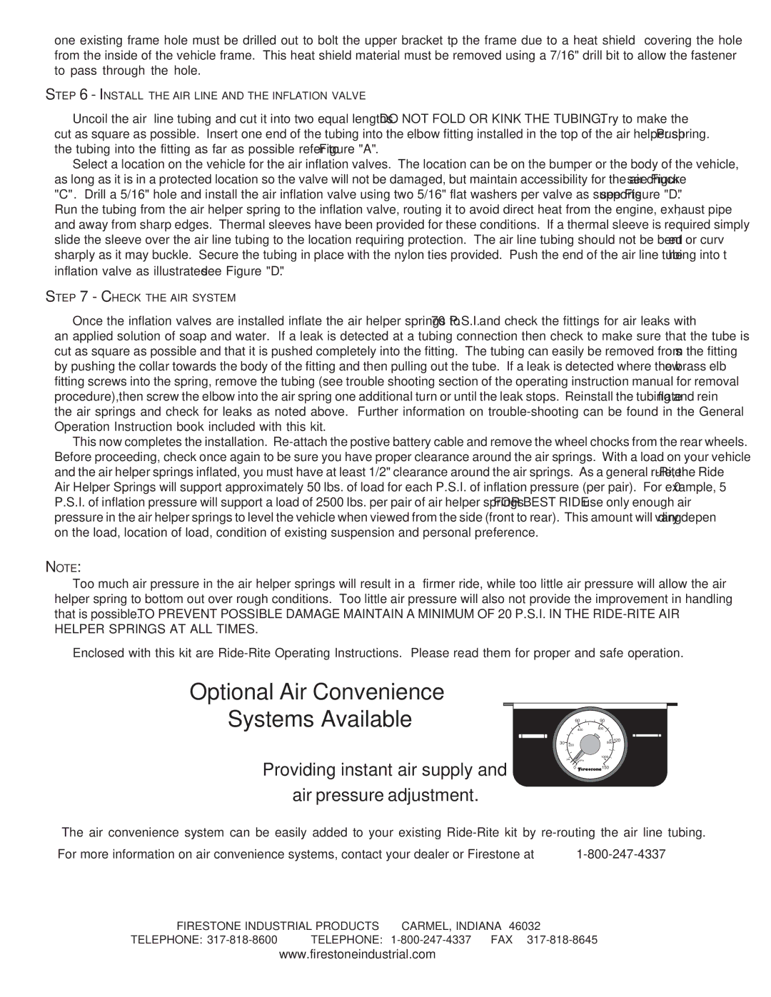
Optional Air Convenience
Systems Available
Providing instant air supply and
air pressure adjustment.
|
| 60 | 90 |
|
| 400 | 600 |
30 | 200 |
| 800 120 |
| psi |
| 1000 |
| kPa | PSI |
0150
The air convenience system can be easily added to your existing
For more information on air convenience systems, contact your dealer or Firestone at
FIRESTONE INDUSTRIAL PRODUCTS | CARMEL, INDIANA 46032 | |
TELEPHONE: | TELEPHONE: | |
www.firestoneindustrial.com