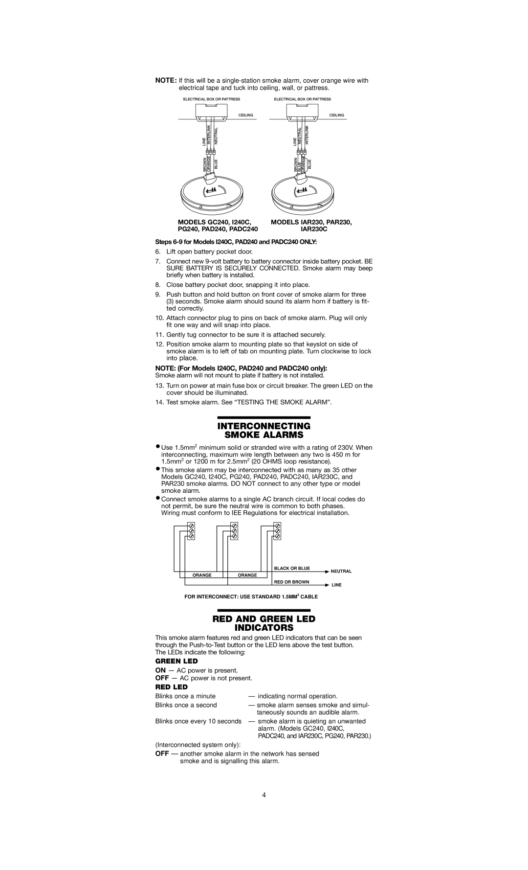
NOTE: If this will be a
ELECTRICAL BOX OR PATTRESS | ELECTRICAL BOX OR PATTRESS | |||
| CEILING |
|
| CEILING |
LINE INTERLINK | NEUTRAL | LINE NEUTRAL |
| INTERLINK |
BROWN ORANGE | BLUE | BROWN BLUE | ORANGE | BLUE |
MODELS GC240, I240C, | MODELS IAR230, PAR230, |
PG240, PAD240, PADC240 | IAR230C |
Steps 6-9 for Models I240C, PAD240 and PADC240 ONLY:
6.Lift open battery pocket door.
7.Connect new
8.Close battery pocket door, snapping it into place.
9.Push button and hold button on front cover of smoke alarm for three
(3) seconds. Smoke alarm should sound its alarm horn if battery is fit- ted correctly.
10.Attach connector plug to pins on back of smoke alarm. Plug will only fit one way and will snap into place.
11.Gently tug connector to be sure it is attached securely.
12.Position smoke alarm to mounting plate so that keyslot on side of smoke alarm is to left of tab on mounting plate. Turn clockwise to lock into place.
NOTE: (For Models I240C, PAD240 and PADC240 only):
Smoke alarm will not mount to plate if battery is not installed.
13.Turn on power at main fuse box or circuit breaker. The green LED on the cover should be illuminated.
14.Test smoke alarm. See “TESTING THE SMOKE ALARM”.
INTERCONNECTING
SMOKE ALARMS
•Use 1.5mm2 minimum solid or stranded wire with a rating of 230V. When
interconnecting, maximum wire length between any two is 450 m for 1.5mm2 or 1200 m for 2.5mm2 (20 OHMS loop resistance).
•This smoke alarm may be interconnected with as many as 35 other Models GC240, I240C, PG240, PAD240, PADC240, IAR230C, and PAR230 smoke alarms. DO NOT connect to any other type or model smoke alarm.
•Connect smoke alarms to a single AC branch circuit. If local codes do not permit, be sure the neutral wire is common to both phases. Wiring must conform to IEE Regulations for electrical installation.
|
|
|
|
|
|
|
|
|
|
|
|
|
|
|
|
|
|
|
|
|
|
|
|
|
|
|
|
|
|
|
|
|
|
|
| BLACK OR BLUE | ||
|
|
|
|
|
|
|
|
|
|
|
| NEUTRAL |
|
|
| ORANGE |
|
| ORANGE |
|
|
| |||
|
|
|
|
|
|
|
| |||||
|
|
|
|
|
|
|
|
|
| RED OR BROWN | ||
|
|
|
|
|
|
|
|
|
|
|
| LINE |
FOR INTERCONNECT: USE STANDARD 1.5MM2 CABLE
RED AND GREEN LED
INDICATORS
This smoke alarm features red and green LED indicators that can be seen through the
GREEN LED
ON — AC power is present.
OFF — AC power is not present.
RED LED
Blinks once a minute | — indicating normal operation. |
Blinks once a second | — smoke alarm senses smoke and simul- |
| taneously sounds an audible alarm. |
Blinks once every 10 seconds — smoke alarm is quieting an unwanted alarm. (Models GC240, I240C, PADC240, and IAR230C, PG240, PAR230.)
(Interconnected system only):
OFF — another smoke alarm in the network has sensed smoke and is signalling this alarm.
4
