BEFORE YOU INSTALL THIS SMOKE ALARM, Continued
ELECTRICAL SHOCK HAZARD. Turn off the power to the area where the Smoke Alarm is installed before removing it from the mounting bracket. Failure to turn off the power first may result in serious electrical shock, injury or death.
•This unit will not alert hearing impaired residents. It is recom- mended that you install special units which use devices like flashing strobe lights to alert hearing impaired residents.
•Installation of this unit must conform to the electrical codes in your area; Articles 210, 760 of NFPA 70 (NEC), NFPA 72, NFPA 101; SBC (SBCCI); UBC (ICBO); NBC (BOCA); OTFDC (CABO), and any other local or building codes that may apply. Wiring and installation must be performed by a licensed electrician. Failure to follow these guidelines may result in injury or property damage.
•This unit must be powered by a
•This Smoke Alarm must have AC or battery power to operate. If the AC power fails, battery
•Never disconnect the power from an AC powered unit to stop an unwanted alarm. Doing so will disable the unit and remove your protection. In the case of a true unwanted alarm open a window or fan the smoke away from the unit. The alarm will reset auto- matically when it returns to normal operation. Never remove the batteries from a battery operated unit to stop an unwanted alarm (caused by cooking smoke, etc.). Instead open a window or fan the smoke away from the unit. The alarm will reset automatically.
•Connect this unit ONLY to other compatible units. See “How To Install This Smoke Alarm” for details. Do not connect it to any other type of alarm or auxiliary device. Connecting anything else to this unit may damage it or prevent it from operating properly.
•This Smoke Alarm has a battery drawer which resists closing unless a battery is installed. This warns you the unit will not operate under DC power without a battery.
•Do not stand too close to the unit when the alarm is sounding. It is loud to wake you in an emergency. Exposure to the horn at close range may harm your hearing.
•Do not paint over the unit. Paint may clog the openings to the sensing chambers and prevent the unit from operating properly.
HOW TO INSTALL THIS SMOKE ALARM
This Smoke Alarm is designed to be mounted on any standard wiring junction box up to a
Tools you will need: •
Make sure the Alarm is not receiving excessively noisy power. Examples of noisy power could be major appliances on the same circuit, power from a generator or solar power, light dimmer on the same circuit or mounted near fluorescent lighting. Excessively noisy power may cause damage to your Alarm.
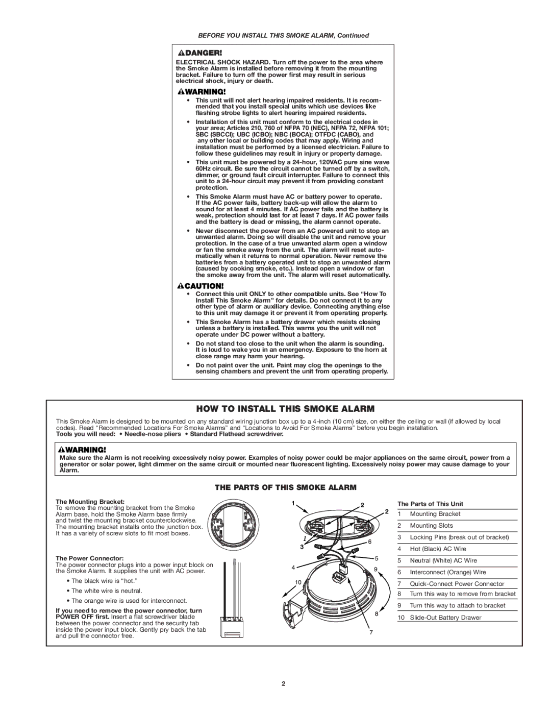
THE PARTS OF THIS SMOKE ALARM
The Mounting Bracket:
To remove the mounting bracket from the Smoke Alarm base, hold the Smoke Alarm base firmly and twist the mounting bracket counterclockwise. The mounting bracket installs onto the junction box. It has a variety of screw slots to fit most boxes.
The Power Connector:
The power connector plugs into a power input block on the Smoke Alarm. It supplies the unit with AC power.
•The black wire is “hot.”
•The white wire is neutral.
•The orange wire is used for interconnect.
If you need to remove the power connector, turn POWER OFF first. Insert a flat screwdriver blade between the power connector and the security tab inside the power input block. Gently pry back the tab and pull the connector free.
|
|
| The Parts of This Unit | |
|
|
| 1 | Mounting Bracket |
|
|
| 2 | Mounting Slots |
| 6 |
| 3 | Locking Pins (break out of bracket) |
|
|
|
| |
|
|
| 4 | Hot (Black) AC Wire |
|
| 5 | 5 | Neutral (White) AC Wire |
4 |
|
| ||
| 9 | 6 | Interconnect (Orange) Wire | |
|
| |||
|
|
| ||
10 |
|
| 7 | |
|
|
| ||
|
|
| 8 | Turn this way to remove from bracket |
|
|
| 9 | Turn this way to attach to bracket |
|
| 8 | 10 | |
|
|
| ||
| 7 |
|
|
|
2