Instruction Manual

Form 2433

November 2007

9500 Valve

result if the partial O-ring faces are not properly supported. Do not use flanges having an inside diameter larger than the maximum shown in table 3.

The NPS 6 to 10 sizes must not be used with slip-on flanges unless flange adaptors are used to support the liner. When using slip-on flanges with other sizes, be certain the valve is carefully centered to ensure that the partial O-ring faces are in full contact with the adjacent flanges.

c.When a flange adapter is necessary, a flange gasket must be installed between the line flange and the flange adapter. Do not use a flange gasket between the valve and the flange adapter. Additional gasketing material at this location could damage the liner.

d.The valve disc must be in the closed position when the valve is being inserted into the pipeline. If the valve disc is not closed, it could be damaged against the mating piping or flanges.

6.Insert the valve into the pipeline. Insert four flange studs or bolts through the flanges to support the valve.

7.Center the valve carefully on the flanges by measuring equal distances at the top and bottom and equal distances at the sides.

8.Insert the remaining flange studs or bolts. Tighten the studs or bolts evenly. Normal flange bolt torques may be used because liner compression is limited by metal-to-metal contact between flanges and the valve body.

9.Rotate the valve disc manually to be certain the disc clears the adjacent piping or flanges as it opens. If necessary, disconnect the power actuator-valve linkage, but do not disturb the adjustment of the turnbuckle or adjustable linkage. If the disc hits the flange, loosen flange bolting temporarily while re-centering the valve. If the problem cannot be corrected in this manner, it will be necessary to use line flanges with larger inside diameters adjacent to the valve.

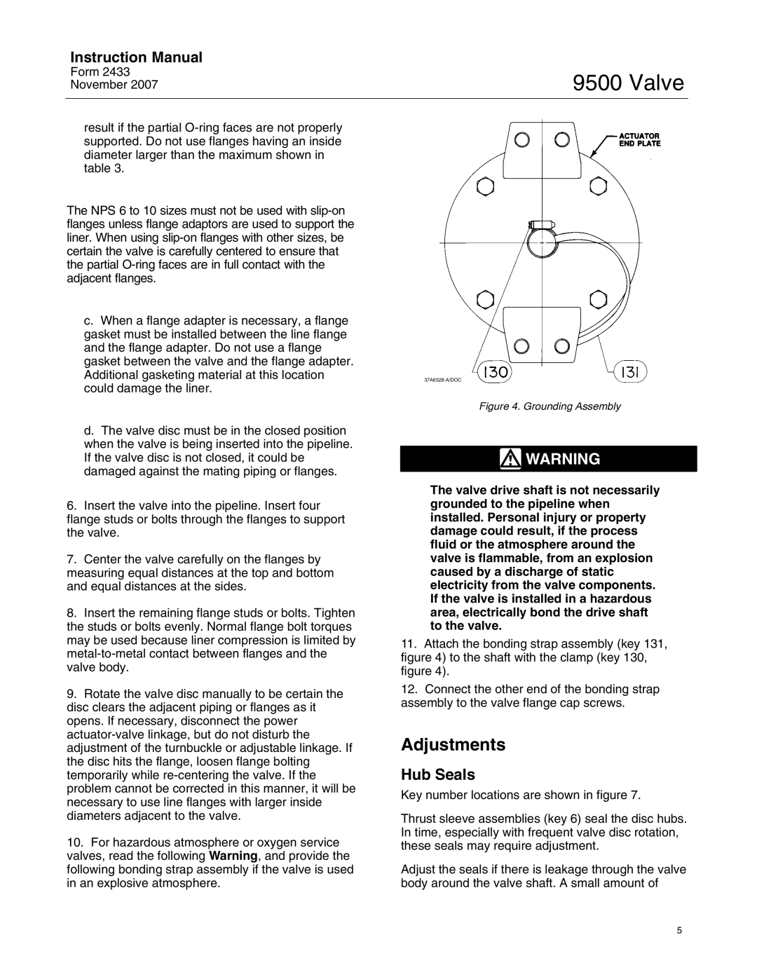
10.For hazardous atmosphere or oxygen service valves, read the following Warning, and provide the following bonding strap assembly if the valve is used in an explosive atmosphere.

37A6528-A/DOC

Figure 4. Grounding Assembly

WARNING

The valve drive shaft is not necessarily grounded to the pipeline when installed. Personal injury or property damage could result, if the process fluid or the atmosphere around the valve is flammable, from an explosion caused by a discharge of static electricity from the valve components. If the valve is installed in a hazardous area, electrically bond the drive shaft to the valve.

11.Attach the bonding strap assembly (key 131, figure 4) to the shaft with the clamp (key 130, figure 4).

12.Connect the other end of the bonding strap assembly to the valve flange cap screws.

Adjustments

Hub Seals

Key number locations are shown in figure 7.

Thrust sleeve assemblies (key 6) seal the disc hubs. In time, especially with frequent valve disc rotation, these seals may require adjustment.

Adjust the seals if there is leakage through the valve body around the valve shaft. A small amount of

5

Page 5
Image 5
Fisher 9500 instruction manual Adjustments, Hub Seals

9500 specifications

The Fisher 9500 is a sophisticated metal detector designed to meet the demands of both amateur and seasoned treasure hunters. This model is celebrated for its advanced technology, exceptional performance, and user-friendly features, making it a popular choice among those who seek hidden treasures underground.

One of the standout features of the Fisher 9500 is its Multi-Frequency Technology, which allows users to detect a wider range of metals and targets. This capability provides greater versatility, enabling the detector to pick up various types of metals with impressive accuracy. Whether searching for coins, jewelry, or relics, the Fisher 9500 proves reliable in any environment.

The device also boasts an impressive depth range, with the ability to detect objects buried up to several feet deep, depending on the size of the target. This depth capability is enhanced by its 11-inch elliptical search coil, known for providing excellent coverage and sensitivity. The size and shape of the coil help in pinpointing targets in challenging terrains, making the Fisher 9500 ideal for both land and underwater use.

Another significant feature of the Fisher 9500 is its user-friendly interface. The detector is equipped with an easy-to-read LCD screen that displays critical information, including target identification, depth indication, and sensitivity settings. This intuitive interface allows users to quickly adjust settings according to their specific needs, ensuring a smooth and productive detecting experience.

Additionally, the Fisher 9500 includes adjustable discrimination settings. This feature allows users to filter out unwanted metals and focus on desired targets. Whether you are scouring a busy beach or exploring an old battlefield, having the ability to customize discrimination settings can significantly increase the success rate of your finds.

The lightweight and ergonomic design of the Fisher 9500 makes it comfortable for extended use. With an adjustable shaft and balanced weight distribution, users can detect for hours without experiencing fatigue. The unit’s durability is another key characteristic, built to withstand the rigors of outdoor adventures.

In summary, the Fisher 9500 stands out with its multi-frequency technology, impressive depth capabilities, user-friendly interface, adjustable discrimination settings, and ergonomic design. It’s an all-around metal detector that helps users uncover treasures with ease and efficiency, ensuring that every outing is a rewarding experience.