
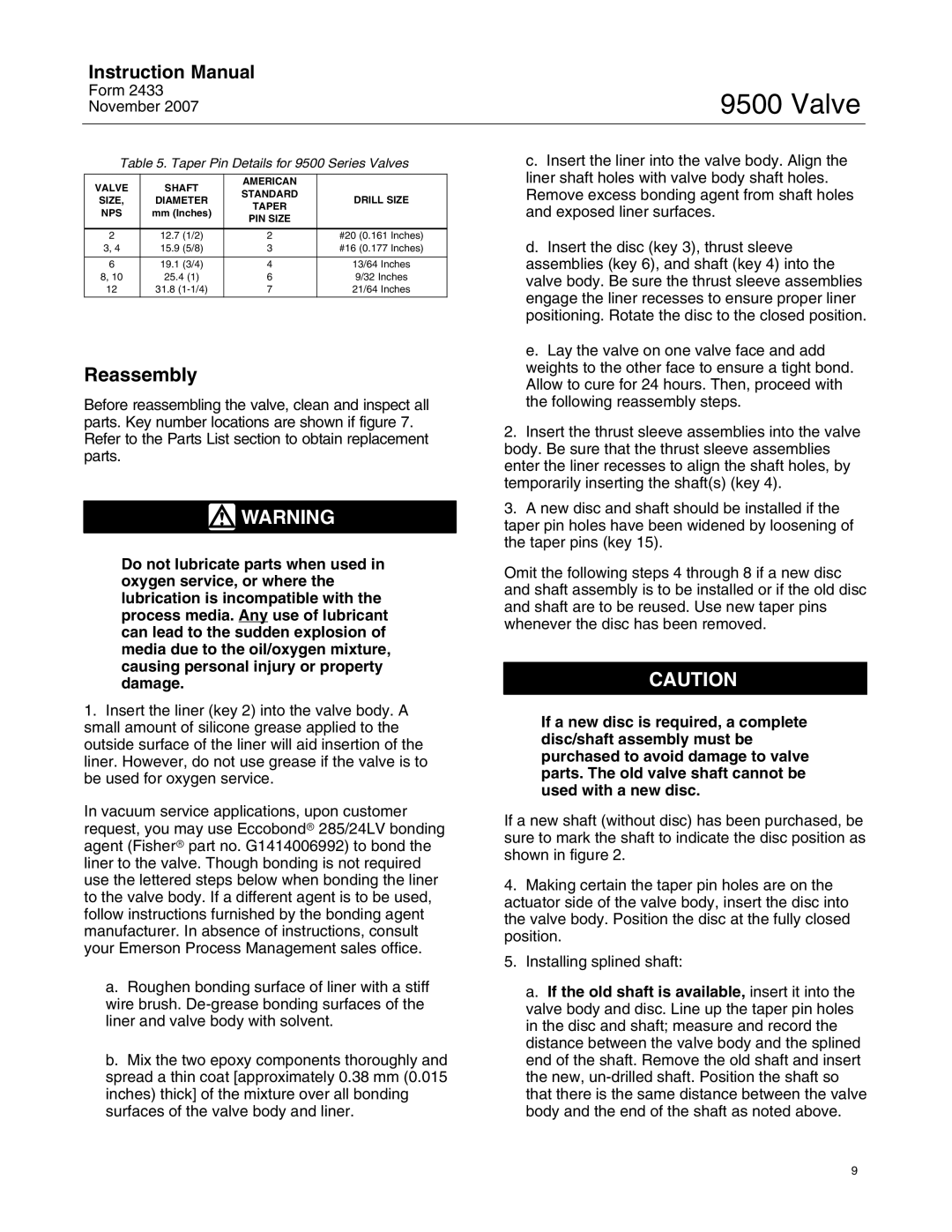
9500 specifications
The Fisher 9500 is a sophisticated metal detector designed to meet the demands of both amateur and seasoned treasure hunters. This model is celebrated for its advanced technology, exceptional performance, and user-friendly features, making it a popular choice among those who seek hidden treasures underground.One of the standout features of the Fisher 9500 is its Multi-Frequency Technology, which allows users to detect a wider range of metals and targets. This capability provides greater versatility, enabling the detector to pick up various types of metals with impressive accuracy. Whether searching for coins, jewelry, or relics, the Fisher 9500 proves reliable in any environment.
The device also boasts an impressive depth range, with the ability to detect objects buried up to several feet deep, depending on the size of the target. This depth capability is enhanced by its 11-inch elliptical search coil, known for providing excellent coverage and sensitivity. The size and shape of the coil help in pinpointing targets in challenging terrains, making the Fisher 9500 ideal for both land and underwater use.
Another significant feature of the Fisher 9500 is its user-friendly interface. The detector is equipped with an easy-to-read LCD screen that displays critical information, including target identification, depth indication, and sensitivity settings. This intuitive interface allows users to quickly adjust settings according to their specific needs, ensuring a smooth and productive detecting experience.
Additionally, the Fisher 9500 includes adjustable discrimination settings. This feature allows users to filter out unwanted metals and focus on desired targets. Whether you are scouring a busy beach or exploring an old battlefield, having the ability to customize discrimination settings can significantly increase the success rate of your finds.
The lightweight and ergonomic design of the Fisher 9500 makes it comfortable for extended use. With an adjustable shaft and balanced weight distribution, users can detect for hours without experiencing fatigue. The unit’s durability is another key characteristic, built to withstand the rigors of outdoor adventures.
In summary, the Fisher 9500 stands out with its multi-frequency technology, impressive depth capabilities, user-friendly interface, adjustable discrimination settings, and ergonomic design. It’s an all-around metal detector that helps users uncover treasures with ease and efficiency, ensuring that every outing is a rewarding experience.